Continue to Site

Eng-Tips is the largest engineering community on the Internet

Intelligent Work Forums for Engineering Professionals

  • Congratulations MintJulep on being selected by the Eng-Tips community for having the most helpful posts in the forums last week. Way to Go!

Steel Column Connection to Concrete Slab - Recessed Pocket 4

Status
Not open for further replies.

KootK

Structural
Oct 16, 2001
18,280
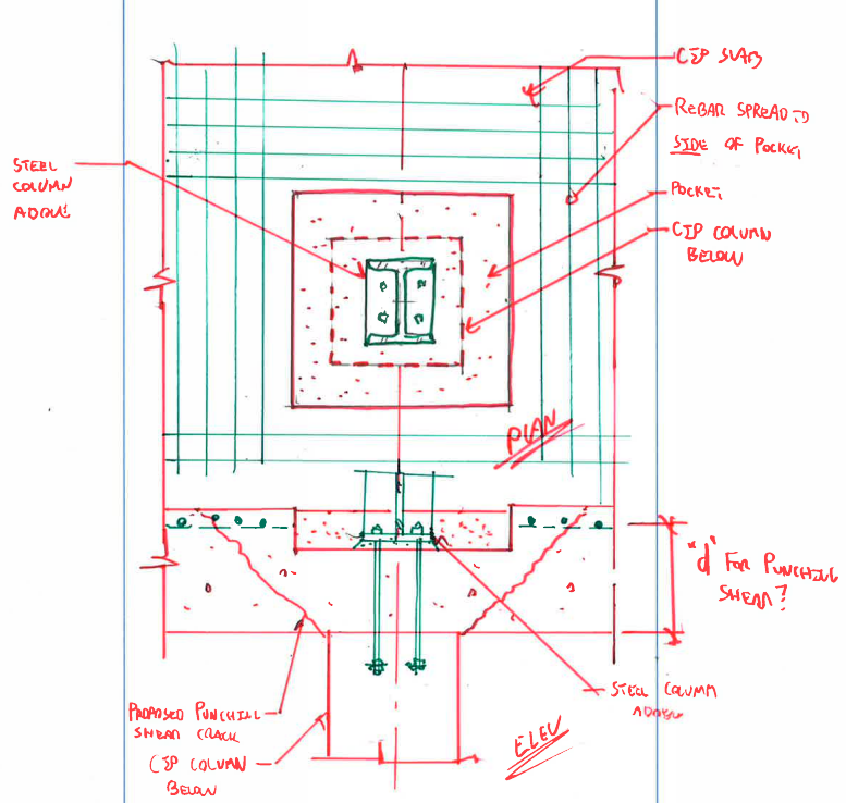
I'm getting pushed pretty hard to use the detail below. The reason is pretty straight forward: compared to a column welded to a cast in plate, plumbing and erection is much easier with this detail. It definitely can be done with the welded detail however.

The photo at the bottom was taken from a related thread on this forum and shows a steel column that is supported directly above a concrete column below. While a consensus has not been reached there, my opinion is that a similar, recessed pocket detail is to blame for the cracking shown.

There are other details that I could use here but that's not what I'm seeking. What I'd like to get feedback on is a method for evaluating whether or not the detail shown below works. What needs to be checked here in order to give this a passing grade?

My specific concerns and opinions are as follows:

1) The recess forces one to either drop the top reinforcing mat or push the bars out to the side of the pocket.
2) With the mat dropped, punching shear is a beast and significant cracking can be expected as shown in the photo.
3) With the top steel moved to the side of the recess, it's tough to meet the code rules on the amount of steel that may be placed over and near the column.
4) With the top steel moved to the side of the recess, I again wonder about punching shear capacity. See the hypothetical cracks in my sketch below. My concern is exacerbated by the interrelated nature of punching shear and flexural capacity (Link) at column/slab joints. If I shift my moment capacity away from the column, does that mess with my punching shear capacity?
5) I have renovated buildings from the 70's and 80's that had similar details but with drop panels. They seemed to be performing well.
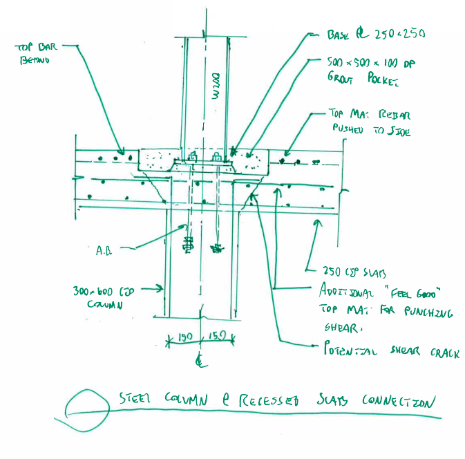
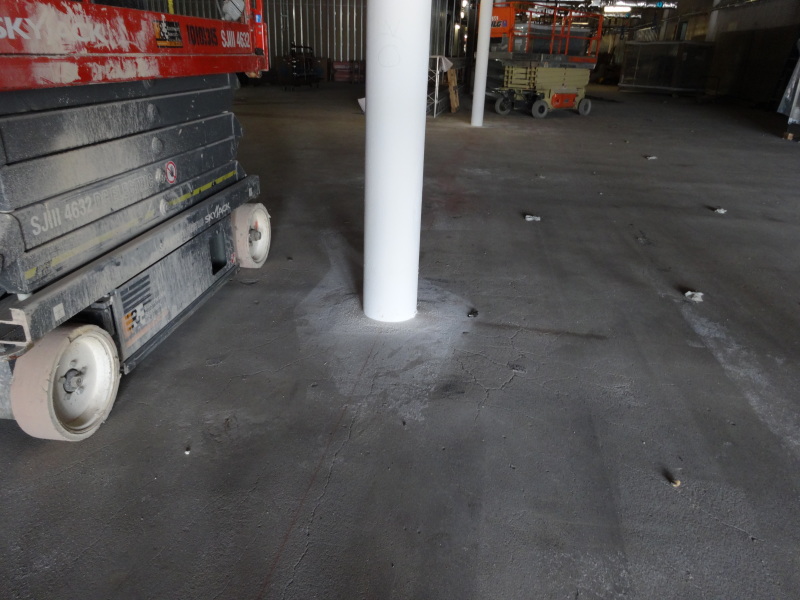
Capture_dskoeg.png

Top_ntux40.jpg


I like to debate structural engineering theory -- a lot. If I challenge you on something, know that I'm doing so because I respect your opinion enough to either change it or adopt it.
 
Replies continue below

Recommended for you

KootK
I've not run into this scenario before, but I do have a curious question to ask. If you have personally run into similar situations dating from 1970's and 80s era construction, what are the specific design principles and resources that were used during that time to successfully design these with dropped panels? Were they simply depressing both layers of rebar to get below the bottom of the grout pocket? How did those details look (beyond the simple fact that they had dropped panels, and your trial detail doesn't)?
Dave

Thaidavid
 
Kootk, you work too hard, it's a holiday.

I'd write something more meaningful but I have to get back to work...

Maine Professional and Structural Engineer.
 
Can you shrink the pocket so that it fits tighter around the column? What about if you had sloped sides of the pocket?

Maine Professional and Structural Engineer.
 
I wouldn't feel comfortable with this detail at all. I would either look into using shear head reinforcement, a column capitol, or a drop panel.

Check out Eng-Tips Forum's Policies here:
faq731-376
 
KookK,

What if you dropped the base plate to the underside of the slab. In other words it was directly on top of the column. The base plate would have to be small enough to avoid the column verticals. I haven't thought of other issues with this but just a thought.

Nick
 
I would have a drop panel of atleast the depth of the pocket, and treat it as a slab fold with lapped Z bars. The detail drawn thrashes both your moment and shear capacity of the slab at the column which is exactly where you need it I would think [ponder]

 
Thanks for the input guys.

thaidavid40 said:
what are the specific design principles and resources that were used during that time to successfully design these with dropped panels? Were they simply depressing both layers of rebar to get below the bottom of the grout pocket? How did those details look (beyond the simple fact that they had dropped panels, and your trial detail doesn't)?

I'm afraid that I'm not in a position to elaborate very much David. They were both main floor slabs at the base of fairly tall steel buildings. The columns were enormous which was probably helpful. The top steel in the slab was called out in the usual way. Unfortunately, the detail showing the column bearing pocket did not show rebar. As such, I don't know the disposition of the rebar.

TheMightyEngineer said:
Can you shrink the pocket so that it fits tighter around the column? What about if you had sloped sides of the pocket?

I could do either or both of these things potentially. How much space one needs to grout a base plate is a question of great interest to me. I estimated 6" all around. If I send this detail the door and it turns out that they can't physically grout the base plate, I'd have to perform Hara-Kiri to preserve my licensing board's honor.

njlutzwe said:
What if you dropped the base plate to the underside of the slab

My concern with this would be construction scheduling. The contractor would have to have the steel columns available before casting the concrete slab. It might also be tricky to plumb the columns without having the slab in place to tie back to. I'm just guessing here. If others know different, please chime in.

I like to debate structural engineering theory -- a lot. If I challenge you on something, know that I'm doing so because I respect your opinion enough to either change it or adopt it.
 
I very much agree that:

1) the proposed detail is questionable and;
2) there are several ways to make improvements (drop panels, shear heads, etc.)

What I'm really gunning for here, however, is a method of evaluating the proposed detail. When someone proposes a cost savings measure, I hate to veto it based on gut feel alone. I do it, from time to time, but I much prefer to have a quantifiable basis for rejection.

I'll ask some more targeted questions and see if that gets me any closer to what I seek. Consider the condition sketched below and the following related questions:

1) Is it valid to calculate punching shear based on the critical section and slab depth that I've proposed below?

2) Given the choice between pushing the top steel to the side of the pocket and dropping the mat below the pocket, which is best? I'll probably do a bit of both.

3) If I am unable to pack the top steel into the 1.5D zone either size of the column, what can I expect the physical implications to be? Severe cracking? Punching shear failure?

4) If I am unable to pack the top steel into the 1.5D zone either size of the column, does that represent an unforgivable code violation? How beholden are we to that clause?

Capture_n9cycq.png


I like to debate structural engineering theory -- a lot. If I challenge you on something, know that I'm doing so because I respect your opinion enough to either change it or adopt it.
 
I won't comment on your evaluation of the proposed detail, as I would just veto it outright.

If the architecture does not allow either the steel column base to be above the slab, or a deepened slab, then another option would be to use a concrete column above.
 
That proposal might have legs Hokie. Thanks for suggesting it.

Even though you'd veto my detail out of hand, I bet that you can still answer at least one or two of my four questions. C'mon... give it a whirl!

I like to debate structural engineering theory -- a lot. If I challenge you on something, know that I'm doing so because I respect your opinion enough to either change it or adopt it.
 
OK, here goes:
1) I would think not, but don't think there has been any testing on that type arrangement, so I don't believe the code provisions apply.
2) You need the depth for flexural capacity.
3) The Australian Standard is a bit different, requiring 25% of negative capacity within the column plus D each side, but I think the main problem with the recess is that, like all recesses, stress risers will develop from the corners. When these cracks form in an already highly stressed area, the unpredictable may happen.
4) I would consider the provision almost inviolate, but all bets are off with the recess.
 
Why do they need such a deep recess? I hope it is for a reason other than making it easier to power trowel? If it is, would something like a Dayton F-54 ductile insert be sufficient for your column loads? I was trying to respect your initial post, but I had to ask.

I was curious about this so I did a quick 3d linear analysis of an example slab with and without the 500x500x100 recess. I assumed the following:
1. F'c = 30MPa
2. Interior slab region modeled. span = 8.0m
3. ft = 2.5MPa (assumed a lower value of concrete tensile strength to amplify cracking)
4. dead load = self
5. Live load = 4.8kPa
6. Simple tensile material model used for concrete effects in tension
7. 15M at 12" o/c top and bottom. I should have spent a bit more time detailing something more appropriate

I am a little hesitant to post, but I will anyway. I have not spent a great amount of time pondering the model. Anyway, here are a few plots in case you are interested.
 
 http://files.engineering.com/getfile.aspx?folder=5a540b03-35fa-43ff-9254-2fcb1555530a&file=slab_wo_depression1.pdf
Thanks so much for the FEM Brad! I regret that I have but one star to give.

I'm actually going to take the printouts into a meeting with me this morning. One can clearly see the stress concentrations that Hokie mentioned as well as the concrete trying to form compression struts around the pocket consistent with my assumptions regarding the punching shear perimeter (which is not to say that the capacity checks out of course).

Brad805 said:
Why do they need such a deep recess? I hope it is for a reason other than making it easier to power trowel? If it is, would something like a Dayton F-54 ductile insert be sufficient for your column loads? I was trying to respect your initial post, but I had to ask.

Thanks for trying to respect my initial post. No worries though, I'll take a good idea wherever I can get one. My parameters are threefold:

1) I can't have anchor bolts or grout showing above the slab and outboard of the column section.
2) I need to provide anchor bolts, or something similar, so that the columns can easily be plumbed and erected.
3) I need to maintain a flat slab soffit.

Those are my mandates, at least, and the reasons for the recess. Something may have to give.

As I fellow Canuck, I have a related question that you might be able to help me with. In the US, there in an OSHA requirement that columns be able to support a minimum eccentric load, cantilevered from the base plate, to provide erection safety. I've been applying it since returning to Canada but am not sure if it's an actual requirement in Canada. Do you know if it is? And, if so, do you know where that requirement resides?


I like to debate structural engineering theory -- a lot. If I challenge you on something, know that I'm doing so because I respect your opinion enough to either change it or adopt it.
 
@ KootK

CSA S16-14, clause 25.2, requires that columns be fitted with at least four anchor rods for erection safety. If you cannot accommodate the four anchors you must take "special precautions'.

I think this answers how its typically handled in Canada, but only for typical cases. For cases without four anchors then some additional thought would be required.
 
No problem, I wish I had more time to work with the model. I would like to see if one could control the cracking better by bundling the bars as you suggested. There are a lot of material models in NLFEA, and typically I will send models back to my PhD guys in EU for assistance when it is something different.

I attached the Dayton Superior insert I mentioned. This would only result in the nut + base plate showing. I would hope you could reduce the recess to the grout thickness. If the arch is so crazy he cannot live with a bolt head showing, egad, what is the world coming too. If it were still a problem I would wonder what they will think when the first cracks happen around the column during the cure?

 
 http://files.engineering.com/getfile.aspx?folder=6344aa3a-1b7a-45d6-ac32-29fb67333654&file=DS_F54.pdf
Well damn. I want some PhD guys in Europe to help me out with stuff...

I should come clean and confess that the 100 mm recess depth was my idea. I thought that would be the minimum to hide the nuts, base plate, and grout and avoid finishing difficulties. If I can use one of those inserts to reduce the recess depth, I certainly will.

I like to debate structural engineering theory -- a lot. If I challenge you on something, know that I'm doing so because I respect your opinion enough to either change it or adopt it.
 
KookK,

What about setting the column on a concrete pier about 3-4' above the slab? That also protects the column from forklift drivers hitting it. In some industrial plants I've worked in they encase the columns after the fact in concrete to help limit damage to the column in the event a forklift hits one.

Thoughts?

Nick
 
njlutzwe: That's a viable option. The trick is whether or not I'd have enough space for the pier. This is architecturally sensitive space rather than industrial. The designer's got some of the columns as W150 which also makes me a little uneasy.

I like to debate structural engineering theory -- a lot. If I challenge you on something, know that I'm doing so because I respect your opinion enough to either change it or adopt it.
 
Status
Not open for further replies.

Part and Inventory Search

Sponsor