Eng-Tips is the largest engineering community on the Internet

Intelligent Work Forums for Engineering Professionals

Steel column design?

Status
Not open for further replies.

n3jc

Civil/Environmental
Nov 7, 2016
187
0
0
SI
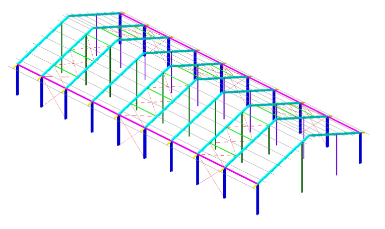
Im designing a steel barn.
I cannot change the position of inner columns (hollow circular section).
Outer columns are H profiles . All columns are pinned at bases.
Inner columns have pinned connections to the bottom flange of a steel rafter/beam.
That means that inner columns do not contribute to the stability of a frame.

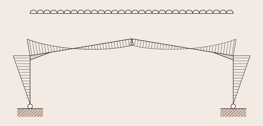
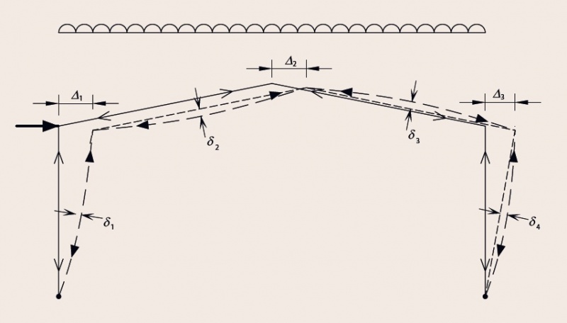
Stabilty of a single transverse frame is based on moment connections between the the top of outer columns and rafters (eaves haunches) and moment connection at the rafters peak (apex haunch). Since I have a large rafter span on the left side of a frame, the frame is tilting towards right side – especially when snow load is applied. Because of this the top of inner circular column has a displacement at the top which are not that small. Im wondering how should I consider this when designing / controling a steeel column section? Inner columns are pretty high. There are only compression axial forces in inner columns – no bending and no shear forces.

What do you think? Thank you for help.


stebri_taphy8.png


3d_hlev_m_sekgp3.png
 
Replies continue below

Recommended for you

If your lateral drift is significant - or even if it isn't - be sure to consider second order effects - the additional lateral force resulting from PDelta.


Check out Eng-Tips Forum's Policies here:
faq731-376
 
Hmm for the middle column which has bending release on top and on the base (pinned connection) i dont think that PDelta is useful. For lateral drift this column is a mechanism.
 
Aketr - I wasn't talking about the design of a single column.

The OP hinted that there was some significant drift to the right in the overall frame.
When this happens, all the columns drift right with it (usually) and all of the vertical load is then eccentric to the column bases.
This creates a second order effect - PDelta - where the overall frame has ADDITIONAL lateral force on it beyond what the initial, first order, analysis reveals.


Check out Eng-Tips Forum's Policies here:
faq731-376
 
But i think that if you make one strong portal frame it's a lot better then this combination with middle moment released columns and weak steel sections. The extra steel used on nodes to take the bending moments are very useful.
You will have something like this:
800px-Portal-14.jpg
 
Where we are, it is quite common to just through diagonal rod bracing in end walls to avoid the large horizontal displacements. Not sure if that is tolerable for you. If this isn't an endwall frame, then you'll need to increase your column and beam sizes appropriately to combat this lateral displacement.
 
n3jc said:
...the top of inner circular column has a displacement at the top which are not that small.

Based upon your displacement graphic, your lateral displacement is 6.75 mm over a column height of 7.84 m - so about 1/1000 - that seems pretty small to me.
 
What limit are you looking to hit? 6mm over a 7m height seems in a reasonable range unless I'm misinterpreting, especially for an unusual unbalanced snow case. It would depend what happens when you combine it with other cases though.
 
n3jc said:
There are only compression axial forces in inner columns – no bending and no shear forces.

Check whether your design code requires a minimum load eccentricity at the top of the column for the connection detail you're using.

 
Tnx for replies.

Inner columns have to be used (not by my choice).
If I remove them I get much alrger cross sections for beams and columns.
This is not what Im allowed to do here.

Well the drift - displacement in attached image is from snow load only.
This drift gets larger in combination with wind and self + pern. loads

Are you guys modeling eaves hunches when controling displacements?

 
OP - ok, I get what you are trying to do. But, in the SLS combination, do you actually get excessive horizontal drift? I don't quite understand what the worry is here - the deflection shown in your diagram is very small and nothing to worry about.
 
Yes, if you're having deflection issues you should probably be modelling the haunch or variable section size if it's significant. Building in efficient stiffness and strength is the whole point of that sort of construction, so it's kind of a waste if you aren't using it for analysis.
 
Status
Not open for further replies.
Back
Top