Eng-Tips is the largest engineering community on the Internet

Intelligent Work Forums for Engineering Professionals

  • Congratulations waross on being selected by the Tek-Tips community for having the most helpful posts in the forums last week. Way to Go!

steel column removal - modify roof joist girder

Status
Not open for further replies.

Ben29

Structural
Aug 7, 2014
313
0
0
US
Hello!
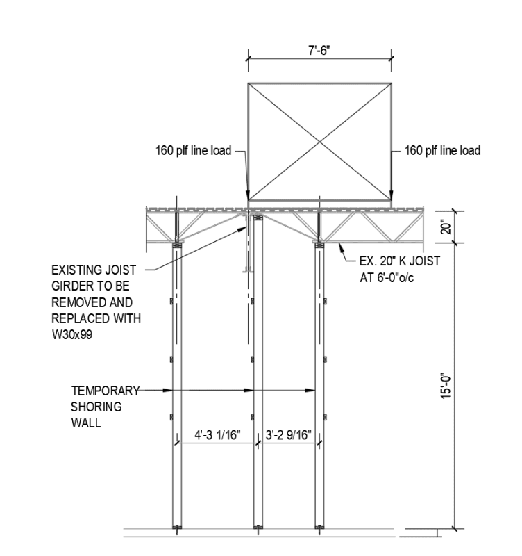
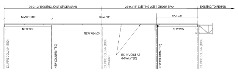
I am working with a 1-story buidling whereby we are removing a steel column. Joist girders are bearing on the column. If we elect to temporary shore the existing steel joist as needed to remove the existing girder, is there a standard practice for how much of the girder you remove?

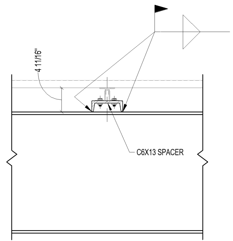
For example, should we keep the top chord of the girder and cut out the web members and bottom chord? Then weld the new steel beam to the underside of the existing top chord.

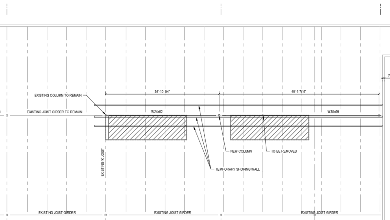
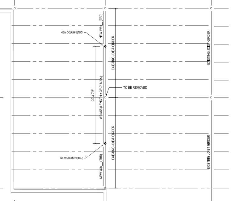
The sketch below shows the new steel beams and columns installed with the existing joist girder completely removed. But now I am thinking that you want to leave the top chord in place since the joist are welded to it.

Screenshot_2023-12-05_144830_tb4a6j.png


Screenshot_2023-12-05_145032_kn0rq9.png
 
Replies continue below

Recommended for you

I would prefer the entire joist removed, and the perpendicular joist seats re-attached to your new girders.

Also I am curious if this element is a drag strut or wall brace. Would need to also re-attach the metal roofing to the new girders with a shear transfer details, and verify girder end connections to transfer axial load.
 
driftLimiter said:
Would need to also re-attach the metal roofing to the new girders with a shear transfer details, and verify girder end connections to transfer axial load.

If the existing joist girders are supporting the existing joists, the metal roofing (decking) isn't attached to the joist girders as the girders would be 2 1/2" below (or more) the decking, unless there are filler tubes on top of the joist girders between the joists.

 
Yes if it isn't a drag strut or wall anchor element it wont likely be blocked, but if you need to transfer axial load into or out of the roof diaphragm it should surely have blocking so that the fasteners can be spaced appropriately.
 
Is it easy to cut the weld between the joist seat and the joist girder?

Will there be access issues relative to welding the existing joist seat to the top flange of the new steel beam?
 
Don't assume a lack of blocking between joist seats means it's not a drag strut for the diaphragm. Vulcraft had (may still have?) a design example to check standard joist seats for rollover due to diaphragm loads. You still had to put that on your drawings so they could design them for it, but it was something of a sanity check to ensure they could design them for it without costly modifications. On smaller buildings with super cost sensitive owners, the cost of adding that blocking or the savings of omitting it could be the difference between getting another job or not from that client around here.

Yes, weld access will be an issue. They'll only have 2.5" to access it. Fortunately, the weld is probably only 2" long. But inspecting it will also be a bear. Any chance they're redoing the roof?

 
Not saying it's a good idea. At the edge you still have an edge angle, and the angle fastens to the joists. Interior yes, you should have it...but that doesn't mean everyone puts it in there...
 
And after posting the above, I do know and realize that many unkowning engineers assume any and all joist seats can transfer orthogonal loading through them without requiring the joist manufacturer to design for the load.

 
The joist seat welds are probably pretty small, so they should be able to shore the joists and grind off the welds, then re-weld with the new W24 beam in place. I'd expect some fit-up issues and need for shims potentially between the seats and new beam.

The idea of leaving the top chord in place is interesting, but it seems a bit too novel and I doubt many people have opted to that route. It seems like a feasible idea and shouldn't change the shoring scheme, but the detailing of the new beam to the old top chord connection could get messy quick. Especially when you factor in uplift, axial loading, etc. Even if the numbers worked out, I don't think I would do it just because the final product would look odd and maybe be a headscratcher for another engineer in the future.
 
I've always kept in mind about 1 kip as the ASD limit for joist rollover capacity that can be designed for without needing HSS fillers or some other method of transfer.

I would also check on cutting all the joists loose if it can be done without damaging the joist top chord instead of leaving part of the girder behind. I recently had a project where they needed to cut a small number of joist loose and reposition them on the girder.

The new W8 girders in the adjacent bays look a little odd, maybe there are strict clearances in those bays. I would increase the depth if possible.
 
XR250 - Page 7 shows a deformed shape of the bearing seat (double angle) where one of the two angle seat sections pulls off the support girder - only the tip of the toe remains in contact with the girder.

This toe-tip is where a small fillet weld is usually placed to secure the joist to the girder.
With this failure the fillet weld is pried open by the rotation - not a good condition for the weld.
Also- the calculations appear to only take into account the lateral shear - not the prying moment on the weld.

The capacity is based on shape (plastic hinges) and the horizontal shear on the weld - not the prying. I'd be hesitant to use this.
The author then goes on (page 8) to suggest use of fillers (tubes) to take the shear instead - what I've typically advocated using.

Weld_Prying_tcnmm2.jpg
 
Ben29 said:
Will there be access issues relative to welding the existing joist seat to the top flange of the new steel beam?

Just throwing out ideas here, but maybe you can use the joist seat erection bolt holes for permanent bolted connections. It would take some accurate field measuring to provide the corresponding holes in the W24 flange, but I suppose it could be done.
 
JAE said:
Also- the calculations appear to only take into account the lateral shear - not the prying moment on the weld.

Perhaps this is why the class was only $40 :)

The connection between the joist and edge angle would surely help this. I generally spec. 2 1/2" tube steel blocking so it is really a moot point for me.
 
Other info on this:

Some comments on pages 93 and 94 here from an SJI seminar.

Page 259 of the latest Vulcraft manual, but there are limitations listed that may not match the usual case. It also appears to be based on the same inelastic failure mode above with the moment arm adjusted.


Seat_sgledw.png


The attached file is from an older Vulcraft manual I had with an elastic moment arm example.
 
I had the site visit yesterday and now my question is this: how do you temporary support the exiting joist to remove the girder if you have an existing RTU to remain in place during the renovation?

The hatched areas in the plan below are large RTU's.

I don't think (3) temporary shoring walls will provide enough room to work around. Any ideas?

Screenshot_2023-12-07_122508_qsputc.png


Screenshot_2023-12-07_jgngei.png
 
That's unfortunate. Don't forget to factor in wind loading/overturning on the unit and the potential for snow drifts on your shoring calcs.

Probably need to be shoring posts/towers rather than walls. Enable can probably give some good ideas if he's around. Otherwise, I'd suggest getting the shoring designer involved early to work out the best solution.
 
Status
Not open for further replies.
Back
Top