Eng-Tips is the largest engineering community on the Internet

Intelligent Work Forums for Engineering Professionals

  • Congratulations waross on being selected by the Tek-Tips community for having the most helpful posts in the forums last week. Way to Go!

Steel component_Guardrail system base connection 2

Status
Not open for further replies.

engineering3DTEK

Structural
Nov 25, 2021
4
0
0
IN
Hello fellow engineers,
AISC design guide 34
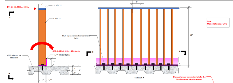
I am designing base connection for a guardrail system. I apply 0.250 kips force on the top rail factored with 1.6 (LRFD), therefore 0.4 kips shear force on top rail. The height of my guardrail system is 42". So I get a moment of 0.4 X42 = 16.8 kip-in momnent at the base connection. But for this force, I am unable to design expansion or chemical anchor base connection. The connection fails. The depth of available concrete slab is just 3" (4000 psi).
Please refer to the attachment (PDF) & image depecting the exact scenario.
Could someone please suggest me how to distribute the forces to anchor bolts & how could I make this connection work.
Thanks you.
Base_connection_Sketch_nhukps.png
 
Replies continue below

Recommended for you

If the railing is fully cantilevered without end connections of the top rail, it is very difficult to get enough moment capacity at the base plate to pass code requirements. When the top rails are anchored, the stress distribution is more reasonable and the base plates take mostly shear and the fasteners also take more shear than tension.

 
Ron, can you explain a bit... I don't understand what you are trying to say.

Rather than think climate change and the corona virus as science, think of it as the wrath of God. Feel any better?

-Dik
 
Dik- I think I know what Ron Is saying.

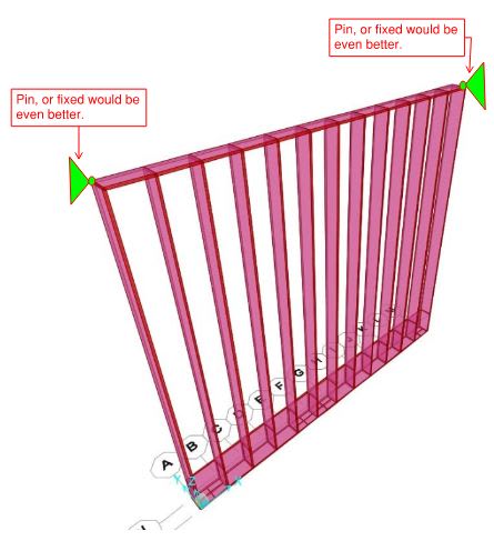
He's saying that the OP currently has full cantilevered action.

If you pin the ends of the rail, then you can generate a little 2-way action which will drop the moment and shear demand on the anchors at the bottom. (see below)

Photo1_y1veiq.jpg
 
Engineering3DTek, please note SandwichEngine’s post and photo above. Guardrails are a critical life safety mechanism and require considerable tried and true strength, no matter what computer software says. Staggering the anchors to create somewhat of a “force couple” may be an improvement over having them in a single line, but I would recommend for the safety of the public that a time tested and conventional guardrail system be used with proper “heavy-duty” posts and baseplates. Working with 1 row of anchors is impractical. Best of luck, sir.
 

I would consider the ends of all BAR material to be fixed, not pinned. My experience is that it is not usually the guardrail that is the problem, but the attachment of it to the concrete. If to steel, it's an easy connection.

Rather than think climate change and the corona virus as science, think of it as the wrath of God. Feel any better?

-Dik
 
Dik-

I'm with you 100% on your reasoning, but I believe the OP is looking at a ~4ft long section of rail that is attached at the bottom, but free at the top. The is some small load distribution between the individual pickets, but not much.

If the ends of the top rail are actually attached to something (which may or may not be possible on the project), then you get true horizontal beam at the top of the rail. Load can escape that way, and thus less goes down to the bottom anchorages.

I think that is what Ron was suggesting. Maybe there is a way to attach the ends of the top rail?
 
If he has a BAR 1/2x2 top rail connected to BAR 1/2x2 vertical posts @ 4' with a bottom rail BAR 1/4x2 and BAR 1/4x2 pickets @ 4". The bottom rail would be 4" up. This is stong enough for guardrail loads. It's simply a matter of connecting it at the bottom. My first comment on this was that the connections he had shown for the attachment at the bottom would have cost a 'bucketfull'. If I were doing this, I'd do it like above, but might use BAR 3/8" stock for durability. By using posts at 4', I'd reduce the number of anchors and seriously look at the anchorage. I don't know if BAR 1/4 will hold up and not bend; it may be too thin. I'd worry about connecting the posts to the deck. This can be problematic for the connection to the concrete at the posts, but I'd look at it. I just checked, the top rail and posts can be BAR 3/8x2.

The top rail should be attached to the pickets and the post, if only by an inch or so of fillet weld.


Rather than think climate change and the corona virus as science, think of it as the wrath of God. Feel any better?

-Dik
 
 https://files.engineering.com/getfile.aspx?folder=f024c5fe-258c-4669-9bf5-e72495c54794&file=NGuardrail_BAR_Pickets_No_Base.pdf
@dik....sorry to take so long...fortunately busy!

fully cantilevered guard rail posts, with no top rail anchorage, induce high moments in the base plates. These are often not resolvable due to waterproofing required under the resisting concrete (balconies, etc), so the embedment of fasteners is low, thus lower capacity. These combinations often result in failure to meet code requirements.

When the top rail is anchored at each end, we then get a benefit of lower load on the posts because of re-distribution of load due to stiffness and anchorage of the top rail. The result is the moment at the base plate is significantly reduced so the fasteners are then resisting more shear than tension and the unity check works.

 
@Ron, most guardrail “systems” do not have the luxury of the top rail anchored at each end - in many cases they’re long runs with jogs and the like. Unfortunately, the battle against the full moment has to be fought at the base with pure cantilevered posts - no getting around it. Fortunately, there’s base plates with concrete anchors that can easily do the job.
 
Nearly all the guardrails I've done are fully cantilevered posts, typically at about 4' centres withs top rail spanning horizontally and bott rail and pickets, or a mid rail at about mid height. Connecting to wood decks/roofs is always fun.

Rather than think climate change and the corona virus as science, think of it as the wrath of God. Feel any better?

-Dik
 
@Engineering3DTEK:

along with the items others have mentioned, be careful using Hilti's anchor software your sketch shows that you are anchoring to concrete on metal deck with only 3" over the flutes but your profis screenshot shows you used the full 5" thickness for the anchor checks. If your anchor embedment exceeds 3" then the profis calculations would be wrong.

My Personal Open Source Structural Applications:

Open Source Structural GitHub Group:
 
@celt83

Celt83 said:
be careful using Hilti's anchor software your sketch shows that you are anchoring to concrete on metal deck with only 3" over the flutes but your profis screenshot shows you used the full 5" thickness for the anchor checks. If your anchor embedment exceeds 3" then the profis calculations would be wrong.

When using profis to analyze anchors over metal deck, I've always considered my slab thickness for the profis input to be equal to the thickness of concrete above the flutes (3" in this case) which ends up limiting me to using anchors with a max embed depth of like 1-3/4 or something around that range.. Is this an over-conservative use of the software? Do you still use the full 5" concrete thickness and just make sure your anchor does not exceed the 3" dimension? I run into this issue all the time with Guardrails on metal deck and often have to get pretty creative with the base attachment.

I'm just a lowly EIT, so I'll end up deferring to what the PE I work for says to do, but I'm just interested in what other people are doing and why.
 
@JDV
Click around on the material selection dialog in profis and you'll see there are a few options specifically for slab on deck. It lets you select which deck profile and concrete thickness and mix you have. And you can mount to the top or the bottom of the deck. I.e., fastening to slab on deck is a different animal, at least in hilti's opinion.
 
Please note this is not on a composite deck, but rather a 12" slab according to an update from the OP. However, the guardrail system in question still weighs approximately 185 lbs for a 4' segment based on a quick estimate, nearly 46 plf or the weight of a small building girder. What I see flawed about the PROFIS analysis and referring to @SandwichEngine's note about theory is that it uses the RIGID plate check box; however, 1/4" thick plate material is far from rigid. In fact, it will tear out or yield an inordinate amount when subjected to the anchor loads of 6,364 lbs shown in the calculation. That is a lot of force on 1/4" steel, but what you can expect when using a lever arm of 1"! HILTI's CBFEM option in PROFIS can illustrate what this non-rigid plate looks like when subjected to these kind of loads. While the guardrail may appeal to architects based on its slim profile, it does not work. It is is not an efficient use of structure and someone may get hurt. Lastly, the constructibility of installing nearly 200 pound guardrail segments with 1/2" anchors appears completely impractical. All the best,
 
I think the other huge problem will be the reality that the anchor could be 1" from the edge of a slab similar to SEngine's image. I think the OP has moved on.
 
Status
Not open for further replies.
Back
Top