Continue to Site

Eng-Tips is the largest engineering community on the Internet

Intelligent Work Forums for Engineering Professionals

  • Congratulations SSS148 on being selected by the Eng-Tips community for having the most helpful posts in the forums last week. Way to Go!

Steel Connection Design 1

Status
Not open for further replies.

Ewi2010

Structural
Nov 6, 2018
3
Hi Guys,

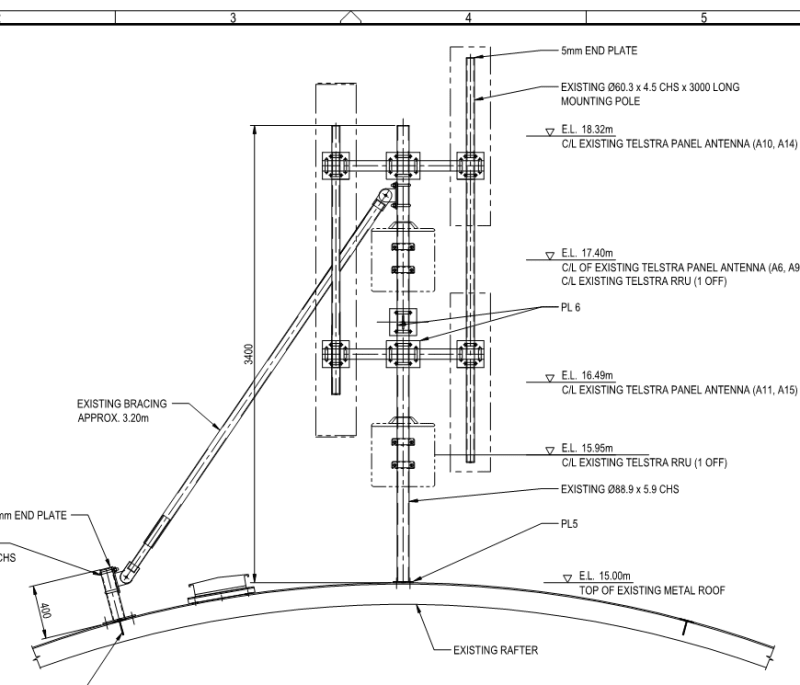
I am new here and a young structural engineer. I am busy checking steel connection on rooftop Telecom structures and I am firstly not sure how there connections would be modeled and then which hand calculations would need to be done ( I am Using Spacegass). Will it be assume that these Ubolt connections are moment connections or not? I was thinking of calculating some sort of yield lines and determining the moment capacity of the plates due to the tension forces in the bolts. Any advice would be appreciated!

Connection_le0zcy.png


Connection1_v47jbx.png


Connection2_mlqpzp.png


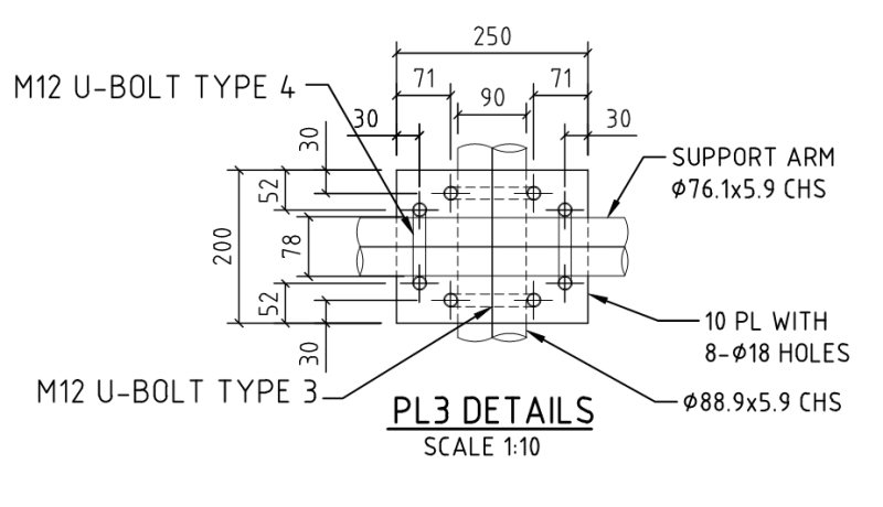
If anyone is willing to help I upload a sample of the type of calc I am doing at the moment.

Thanks in advance!
 
Replies continue below

Recommended for you

In short, you need to design for the end forces developed in your members. It looks like you're responsible for the design of the structure and the connections (sometimes connections are delegated)...which is good, because you might find it more economical to change your design assumptions rather than be stuck with unreasonable connection forces - for example, maybe its cheaper and easier to use a simple span beam with pinned connections instead of a beam with fixed connections. The beam in the simple span condition might be heavier, but the connection much simpler and cheaper.

When designing connections, the one thing that has to stay in your mind at all times "how are they going to erect this?". You can analyze a connection to death, but if your structure can't be assembled because you didn't consider erectability, you're in trouble.

As far as the calcs for specific connections - if you post specific questions about your process, you'll get good answers here.
 
Thanks for the reply CANPRO, this is existing structures where antennae will be changed and thus the loading altered. My question is how to check that plate to which the U bolts and pipes are connected? I wish I can make it more specific but its basically the whole concept I'm struggling with. This probably starts with the modeling of the structure. Will my nodes at the points where these connections occur be modeled as to not carry any moment or will they carry moments. I f they do, as I model them now, I use the moments and forced to calculate the moment resistance of the plate. I will add a sample calc for you to see my thought process.
 
 https://files.engineering.com/getfile.aspx?folder=ab856a8b-4a8f-4cf7-a1c3-9a5a31b7b6e1&file=SKonica_Min18110614500.pdf
To get moment transfer from a pipe to a perpendicular pipe, the U bolts would have to work in friction since one pipe would be trying to torque itself free from th U bolt. You might have some limited moment capacity but I wouldn’t count on it.

Check out Eng-Tips Forum's Policies here:
faq731-376
 
When checking crossover plates for antenna supporting structures I will avoid treating crossover plates as moment connections if I can. If I am forced to treat them as moment connections (typically for stability reasons) what has always governed for me is the clamping capacity of the u-bolts. I have not come across a situation where the plate itself was the governing factor. I do not know anything about the software you are using, but I use RISA. In RISA if you have crossing members connected with a node, RISA will treat it as a moment connection. To treat it as a pin connection you have to offset the members and connect them with a rigid link and from there you can set the individual releases of the rigid link so no moment is transferred.
 

I think we need to see the whole roof structure to answer your question.

How is the MY moment generated, is the 88.9 CHS member cantilevering from 76.1 CHS horizontal member? If that is the case a U-bolt connection detail is not appropriate.
 
You guys are awesome, thanks for the help so far! I will attach some more info f=to make it more clear. With this software I can specify the x,y,z connection for forces and moments (Fixed or released) for each member. In the second picture you can see the circles at the end on the member which indicate that it is released about that axis for moments.


Connection4_dxpfgn.png


10904_BERP_External_Audit_Photos_14_ii1ph8.jpg


Connection3_ja6iwb.png
 
Looks like it would be notionally unstable if you don't treat the connection between outrigger and main post as a moment connection, putting torsion into the post.
 
The connection between the main post and the bit hanging off will have to resist some torsion, as noted above. The connection will also have to keep the hanging portion from sliding down...I believe the torsion and sliding resistance will have to be provided via friction/clamping. For the remainder of the connections, I'd first try to model and check all connections as pins only.
 
You can treat your antenna pipe's connection to the horizontal pipes as pinned, but will be forced to check the horizontal pipes connection to the center pipe as fixed. Which code are you using for this site? It may address how to check the clamp connections. If it does not, then it will be up to your engineer judgement on how to check it. I have talked to other engineering groups and some manufacturers on clamp connections and their is not a consensus on how you check them.
 
Status
Not open for further replies.

Part and Inventory Search

Sponsor