Continue to Site

Eng-Tips is the largest engineering community on the Internet

Intelligent Work Forums for Engineering Professionals

  • Congratulations SSS148 on being selected by the Eng-Tips community for having the most helpful posts in the forums last week. Way to Go!

Steel connection - help me understand 3

Status
Not open for further replies.

mats12

Geotechnical
Dec 17, 2016
181
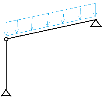
I was inspired for this from looking at other thread.

Im really confused as far as steel connection goes and how is it considered for design/in the model.

STEEL_CONN_caahmp.png


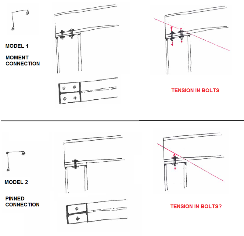
MODEL 1: I understand this is a moment connection between a column and a beam. Since there is a moment, we have tension force in bolts.

MODEL 2: this is supposed to be a pinned connection? Is there any tension in bolts there since there are no moment? I mean there will still be a rotation around columns flange that wants to tear a bolt apart, isnt it?

Any ebook, article about things like this, from where Id be able to learn?

regards
 
Replies continue below

Recommended for you

I would consider both connections to be pinned.
 
But how do you design bolts then? Based on what forces?
 
I agree with homie, it's pinned.

You ask what are the bolt forces. You need to show how it will be loaded.
 
That type connection normally just resists uplift. So all the bolts are assumed to be in tension. Used in post and beam construction, or braced frame construction, not in rigid frames.
 
LOAD:

loaded_ewz0pc.png


I wasnt expecting that... interesting...

I suspect you design bolts on shear forces (if there is a axial load in beam), but im really wondering is there any tension in bolts since the end of a beam is trying to rotate upwards (around colums flange)? If yes, then how do you get this forces if there is no moment (pinned connection not moment)?
 
A couple things:

Most would consider them both to be pinned connections. Model 2 for obvious reasons. Model 1 - because the bolts are inside of the flanges and the members would need to rotate A LOT in order for such tension to develop. Most likely the building would be braced some other way and that much rotation would not occur. If the member end plates were longer and the bolts were positioned outboard of the flanges this would be considered a moment connection.

The loading case that wold result in tension is likely to occur when this joint is at the leeward wind side. Buildings like this will often have a lightweight roof.

 
mats12 said:
but im really wondering is there any tension in bolts since the end of a beam is trying to rotate upwards (around colums flange)? If yes, then how do you get this forces if there is no moment (pinned connection not moment)?

I think that your instincts here are spot on. Both connections will transfer some moment whether the designer intended it or not. As such, the bolts will see some tension very much as you proposed in your sketches. Two things that you'll have working in your favor if you considered this a pin connection include:

1) Transverse bending flexibility in the beam flange.

2) The beam will generally tend to be stiffer, and rotate less at the support, if it is designed assuming a pin connection.

Really, the bolts being close to the compression flange of the column serve to increase the tension on the bolts. Same rotation tendency but a smaller lever arm to the bolt.

So why do we ignore these bolt tensions in practice?

- Structural engineering's a rough science.
- Bad things don't seem to happen.
- Reasons #1 and #2 above.
- You could probably yield the bolts in tension and retain uplift capacity.
- Shear demand on the bolts will generally be very small.


I like to debate structural engineering theory -- a lot. If I challenge you on something, know that I'm doing so because I respect your opinion enough to either change it or adopt it.
 
Status
Not open for further replies.

Part and Inventory Search

Sponsor