Eng-Tips is the largest engineering community on the Internet

Intelligent Work Forums for Engineering Professionals

Steel Connection Solution for Cope Yielding

Status
Not open for further replies.
Replies continue below

Recommended for you

Depends on what you mean... are you looking for ways to eliminate the fabricator from actually coping the beam or ways to eliminate the typical failure modes associated with them?

Your solution of of an extended shear tab would take care of both (provided the extended tab works for buckling as well). There are also some major advantages to erecting beams since they can be dropped in straight instead of "swung" in (not sure if that's even a word). Cost would vary from fabricator to fabricator but in general these extended tabs would likely cost more if they needed to be welded to the top or both flanges.

As far as strengthening a coped beam, you can:

1. Weld a plate to the top of the coped web to create a false flange.
2. Weld a "doubler" plate flat on the web the extends past the cope to effectively thicken the web section prone to buckle.
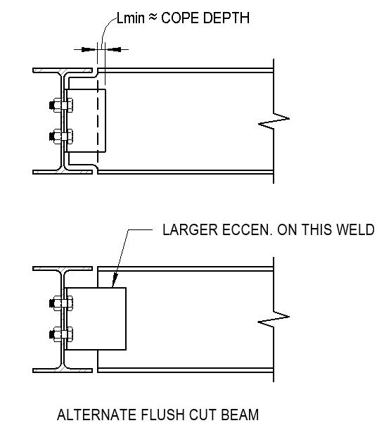
3. You could use clip angles with longer in-standing legs that extend up to or past the cope that achieves a similar effect to #2.

I'm sure there are other ways but these are all options I've used in the past.
 
T_Bat - Thanks for the reply. There are some W8 beams that don't work due to a cope. It sounds like the extended tab is the way to go, but I wanted to see what other common options there were.
In this case it has come up during the shop drawing / calculation review, so I'm also trying to gauge how the fabricator will respond to the suggestion.

EIT
 
A couple other options we use from time to time if you have some control over the beam size. (Option 2 may not work for composite beams.)

1 - Use a deeper beam such as W10x12 instead of W8x10 the small added weight may cost less than a complex connection.
2 - lower the W8 beam below the flange and provide a continuous spacer to the deck/slab and use a non-coped standard connection. (such as lower the W8 1.5" and weld a C4x4.5 toe down to the top flange.
 
T-Bat:
Regarding your option 3 from your first post. How would you design the angles? would you check the in-standing landing for the larger eccentricity? Then also make sure you meet the the ductility requirement somehow?

Thanks


EIT
 
Depending on the cope length - the in-standing leg may not even be that large. Their design would essentially be the same as a standard shear connection. Rotational ductility is related to the thickness of the outstanding legs so again, these typically would be the same design procedure as a standard shear connection. There could possibly be a larger eccentricity on the weld of the in-standing leg.

Part 9 of the AISC manual has recommendations on the design of doubler plates for coped beam reinforcement (see pg 9-17 of the 14th edition manual). I would check the in-standing leg of of these angles using that procedure.

Capture_xl24ag.jpg


As an aside, part 9 of AISC also includes the following language before the coped beam checks (pg 9-6):

"For beam ends with short coped no greater than the length of the connection angle(s), plate, or tee, flexural local web buckling will generally not occur." Typically if the in-standing leg of the connection extends up to or past the cope this is rarely an issue.
 
Status
Not open for further replies.
Back
Top