Continue to Site

Eng-Tips is the largest engineering community on the Internet

Intelligent Work Forums for Engineering Professionals

  • Congratulations cowski on being selected by the Eng-Tips community for having the most helpful posts in the forums last week. Way to Go!

Steel Connections weaker than Members in Seismic Analysis 4

Status
Not open for further replies.

Blackstar123

Civil/Environmental
May 5, 2013
253
I am checking the design of an existing steel structure. This is an industrial building which was originally designed for UBC seismic zone-2A. But now clients want to check if the same design will be able to resist the UBC seismic zone-2B earthquake forces.
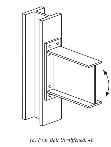
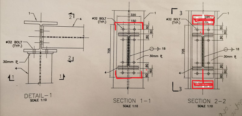
A number of steel members have design capacity ratio within the range of 0.4 to 0.6. Whereas, their connections have ultimate design force very close to, or greater than the actual capacity of connections. All of the frame connections are End plate moment connections.
My question is can I release the moments from end such that connection become adequate to resist the ultimate forces? I am not comfortable to do so because of the brittle nature of high strength bolts.
My other concern is that we design buildings for inelastic earthquake force, taking advantage of the plastic deformation at beam ends. In this case, I do not think that I can justify reducing the seismic forces, since some connection will reach their ultimate capacities way before any plastic hinges are formed in the members.

I have been visiting this forum for a while now but this is the first time I am posting here. I will really appreciate any help i can get regarding this topic.

Euphoria is when you learn something new.
 
Replies continue below

Recommended for you

If it requires breaking the connection to provide a moment release, then you cannot release the moment in the model, because the model would not reflect reality. At that point, you have a failure, not a release.

Rod Smith, P.E., The artist formerly known as HotRod10
 
Rod said well. You have to hand check the ductility of the connections to produce/accommodate the rotation caused by seismic effect, and modify joint specification accordingly, if possible. Otherwise the connections would just break and become simple connections. The structure may, or may not fail immediately, depending on the force level and overall ductility of the building, but, it may not be restored to the original condition and would require retrofit works.
 
If they are moment connections, the you might consider the following to STRENGTHEN the connection.
a) a haunch connection. Essentially weld a WT to the bottom of the wide flange. The WT will reduce flange forces in the moment connection and allow the plastic hinge to form in the un-reinforced area of the beam.
b) Cover plate the moment connection (though I'm not as big of a fan of this). This doesn't reduce the force in the welds at all, it actually increases them slightly, but it does push the plastic hinge off into the beam.

There are other methods as well, though none jump immediately to my mind. AISC does have design guides that might help 12 = Modifications of existing steel moment frame connections for seismic. 15 = rehabilitation and retrofit.
 
Thank you all for your responses.
BridgeSmith and retired13, your reasoning makes complete sense. Just to make it all clear, what i now understand is that we can design a connection to be partially restrained as long as the joint forces from analysis are less than the capacity of the connection. Otherwise as in my case (i.e. end plate moment connections) if bolts are weaker than the end plate, than it may result in bolt failure before plate starts to yield and moment redistribution can occur.
JoshPlumSE, your suggestion about haunches have merit. I have spend hours on thinking how i could reduce end moments from my members, employing some global changes in my model. But reducing the couple force using local measures did not come into my mind. Since I have never design a haunch connection before, I've to look into its design consideration. Can you refer some book or other good reading material?

Euphoria is when you learn something new.
 
Blackstar123,

Depending on the geometry, before breaking the bolts, the end plate may still have room to rotate to allow for release some of the energy, so the member will pick up the redistributed moment. If that's not possible, then the connection will fail (been too rigid). I think a FEM analysis on the connection is warrant.
 
AISC Design Guide 12 - Modification of Existing Moment Connections has some good stuff on haunches. I prefer the "Straight Haunch" shown in Figure 2.4 rather than the angled haunch shown in Figure 2.3. I did some of these types of connections in the late 1990s. Even though we were only doing OMF's, it was a lot easier to justify haunched connections in the aftermath of Northridge. Moving the plastic hinge away from the connection. Lower concentrated forces at the column weld connection. Just much easier to get through plan check at the time.

That AISC design guide also shows a bolted bracket connection to reduce forces in the weld. But, I've never done that.
 
Blackstar123,

I am not taking back my assessment that says there is potential ductility in the connection that you can utilize, but it is only good for the purpose of discussion, I don't think you would/should really go the length to prof it and bank on it, as it is deviated from code, and the failure could be deadly and intolerable. Because you are upgrading the structure, I think it is the best time of opportunity to upgrade/strengthen the connections to meet the increased strength demand. Since the utilization ratio of the members are load, looks like you are in a good shape. Why not upload sketches of the connection, so more people can comment on it with good ideas.
 
Retired13,
Thank you so much for your responses. I really appreciate it.
Initially, I wanted to release some forces from the connections since most of the steel members have ample margin in demand capacity ratio. But as pointed in above posts, that force release will probably happen in case of bolt or weld failure (provided that bolts or welds are the weaker link in the provided connections). Ductile release of force may be possible if the end plate started to yield.
The connections i have checked so far are proportioned such that almost equal safety factor is provided in thickness of plate, thickness of flange weld and dia of bolts.
That's why I've abandoned the idea of releasing the forces from connections and now I'm thinking more in line of how to strengthen them.
I'll sure to attach some example connection next time I'm in office. But most frame connections are in unstiffened 4 bolts end plate connection for W18x76 beam with 30mm thick plate and M24 bolts.

Euphoria is when you learn something new.
 
unstiffened 4 bolts end plate connection

My immediately thought is that sounds "quite flexible", as opposed to more rigid moment connection that usually will have more bolts, and even with stiffener plates back in the column. Please do upload a few simple sketches to gather more thoughts, and ideas, if strengthen is desired.
 
image_mdawr4.png


Retired13 -

It's actually 4 bolts on the tension side. AISC considers it a fully restrained moment connection.
 
I should also note that this is the most common type of moment connection in the petrochem industry.... Because it doesn't involve any field welding. That's very important when the facilities you're working at have large amounts of flammable materials everywhere.
 
I see, thanks. There is room for rotation, but not allowed by code (column flanges, and end plate between bolts).


[ADD] If this is the case, I'll try adding tension/compression stiffeners first, if field weld is permitted.
 
My last comment was not on the point, please consider strength by:

1) weld beam end plate to the column, or
2) enlarge bolt holes to accept larger bolt, or
3) add bracket below the beam.

After chosen any method above, you will need to ensure stiffness of the column flange is adequate to resist the added tension load, then add tension/compression stiffeners as required.
 
I have checked column flange for stiffening requirements. Since column flanges are very thick (=33 mm), no stiffeners are required.
I've attached below the sketch of connection.

Euphoria is when you learn something new.
 
 https://files.engineering.com/getfile.aspx?folder=bb30c1f0-80c8-4f91-aa01-97b2f5929ea9&file=IMG_20200120_102310.jpg

Thank you all for your suggestions.
I've already proposed to increase diameter of bolts in some connections. And now adding brackets in main frame connections where required.

I am retrofitting column splice connection by adding a plate on inside of the flange so that bolts are in double shear. I have checked this connection for Dead+Live condition and found out that half of the provided bolts are needed to resist the axial force in the connection. I've added the note in the connection to add the plate on each side of the flange in a sequence wise manner and not to open all the bolts together.
Since you have proposed to increase dia of holes, i would actually like to know if there are some necessary precautions which should be observed before and after opening the connection bolts. I searched the web for possible precautions but didn't find anything helpful.


Euphoria is when you learn something new.
 

The building is part of cement mill building and have lots of small belt conveyors conveying material which are not flammable. Also filed welding is not restricted as long as it doesn't hinder the daily plant operation.

Euphoria is when you learn something new.
 
I am retrofitting column splice connection by adding a plate on inside of the flange so that bolts are in double shear. I

Please note connection below does not put bolts in double shear.

d_lai1ui.png
 
Retired13, I'm aware of what you are conveying about double shear and I agree its a very simple mistake some engineers are not even conscious of making. Rest assured the connection plate i'm adding will connect flanges of both column together.

Euphoria is when you learn something new.
 
Just want to let you know that I made the same mental mistake in the beginning too. I thought that it would be fine if the added plate was to be welded to the column flanges. Wrong, it will move with the column, so there is still only one shear plane when the beam moves in opposite direction.

A few details for your consideration. Welding can be considered when connecting to column flange. For connecting to column web, I suggest to add bracket(s) as shown - a pair shorter bracket if there is available space to add top bracket; or a deep bracket below the beam, mainly to assist in taking care of the gravity load (shear).

end_plate_1_cra0fq.jpg


Section 3-3
Bracket_emqyrp.png
 
Status
Not open for further replies.

Part and Inventory Search

Sponsor