Continue to Site

Eng-Tips is the largest engineering community on the Internet

Intelligent Work Forums for Engineering Professionals

  • Congratulations KootK on being selected by the Eng-Tips community for having the most helpful posts in the forums last week. Way to Go!

Steel Frame Connections - Specific connection type

Status
Not open for further replies.

kellez

Civil/Environmental
Nov 5, 2011
276
Hi everyone, what I want to do here is to start a general discussion regarding steel frame connections, real life stiffness of connections, how do you choose to model them for analysis, how you choose a certain type of connection over another and why.

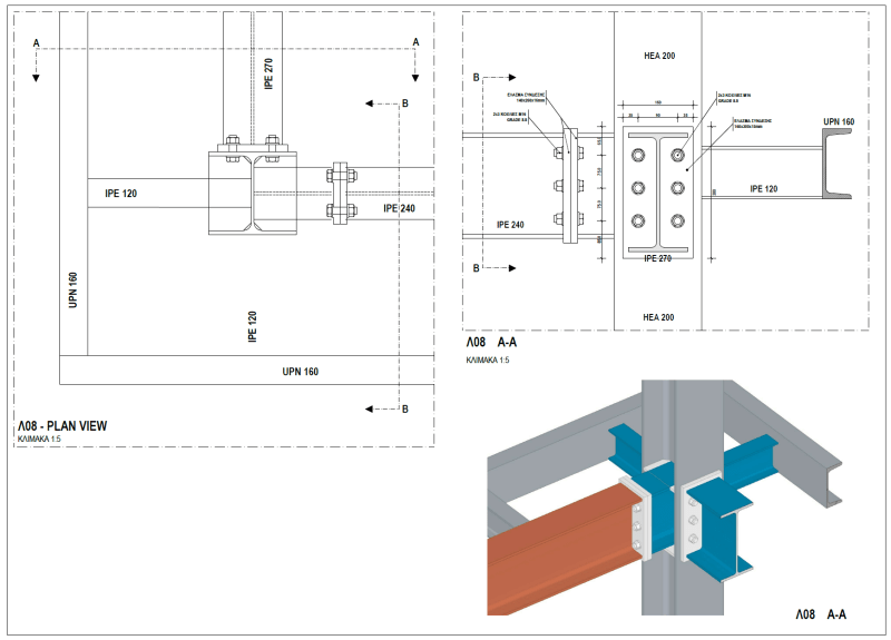
In order to start this topic, i am posting a model/photo of a simple connection. and my question is, what do you think about the connection of beam IPE270?

My thoughts are....for sure this is not a fully fixed connection but neither a fully pinned one. My thinking, is that it actually does, absorb some moment but the question is how much?
If we remove the 2x M16 bolts at the top and the 2x M16 bolts at the bottom and we only leave the 2x M16 bolts in the middle then for sure the connection will absorb less bending moments than the connection with all the 6x M16 bolts.

what do you guys think?


Connection_1_anllnr.png
 
Replies continue below

Recommended for you

Depends on the torque level in the bolts and the resulting amount of joint clamp-up. Of the joint does not gap then it will transfer moments. Obviously with fewer bolts the moment required to gap the joint is lower.

And with only the two center bolts the light grey attachment plate is likely to bend which might result in the welds failing.
 
Ok that sounds reasonable, resistance of moments also depends on the amount of contact between column and beams.

Then lets say I want to analyse the structure, how would you model this connection between beam IPE270 and column HEA200?
CASE 1: I can either model it fully fixed and use the results to design the connection as fully fixed and in turn design the beam accordingly.
CASE 2: Or i can model it pinned and use the results to design the connection as pinned and then design the beam accordingly which obviously will
require a bigger section than CASE 1 above due TO A bigger moment in the middle of the beam.
 
Your case 1 and 2 for that connection specifically is always the case. Unless the moment connection is required for lateral stability of the overall frame.

In my opinion, if I were modelling it based on the connections I'm seeing, the IPE270 and the IPE240 would both be modelled as fixed, I can't see the details for the IPE120s well enough to comment, but based on the overall geometry at this corner, they would also be considered fixed. It looks like their intent is to be outriggers.

Now, if you determined that the column didn't have the capacity, or the connection didn't, to provide the fixed end moments for the beams, but the beams would be stiff enough to work as simple spans, I might not have an issue anyway. Provided the fixed end moments on the beams aren't required for overall frame stability.
 
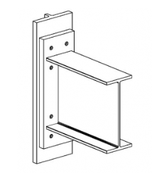
The IPE 270 is just a bolted end plate moment connection. Essentially a "flush" end plate connection. Those are usually modeled as "fixed". However, AISC would probably call them "partially restrained" instead of "fully fixed" per the moment rotation curve. I wouldn't use these for seismic connections as seismic connections.

It would perform a little better (i.e. fully fixed and appropriate for seismic loading) as as EXTENDED end plate connection. Where the plate extends further above and below the flange. Just enough so you can get a row of bolts above and below the flange.

Take a look at AISC Design guides 16 and 4. You'll see Design Guide 16 has connections just like yours and talks extensively about them. Design Guide 4 (on the other hand) focuses on seismic connections, which you'll see is limited to the extended version of end plate connections.

bolted_unstiffened_end_plate_moment_connection_rxacoo.png
 
In the real world, connections are never fully fixed, and rarely truly pinned. They're pretty much all partially fixed. It's a matter of where it is on the continuum, and how closely does the fixity need to be approximated.

Depending on how important it is to get close to the actual fixity, you can narrow the envelope using very detailed analysis methods and models.

At the other end of the spectrum, you can assume the connection fully fixed, analyze the structure, get the loads, reactions, stresses, etc., and then do the same with the connections assumed pinned. Sometimes, there's not alot of actual difference between the two 'extremes. If the member sizes, deflections, etc. don't change much accounting for those 2 possible extremes, then honing in on the actual fixity may be unnecessary.

Rod Smith, P.E., The artist formerly known as HotRod10
 
Status
Not open for further replies.

Part and Inventory Search

Sponsor