Continue to Site

Eng-Tips is the largest engineering community on the Internet

Intelligent Work Forums for Engineering Professionals

  • Congratulations KootK on being selected by the Eng-Tips community for having the most helpful posts in the forums last week. Way to Go!

steel moment connection 5

Status
Not open for further replies.

n3jc

Civil/Environmental
Nov 7, 2016
187
I have a steel frame.
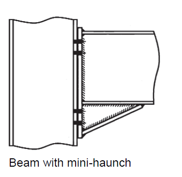
Connection between column and beam has to be a moment connection (stiff/rigid).

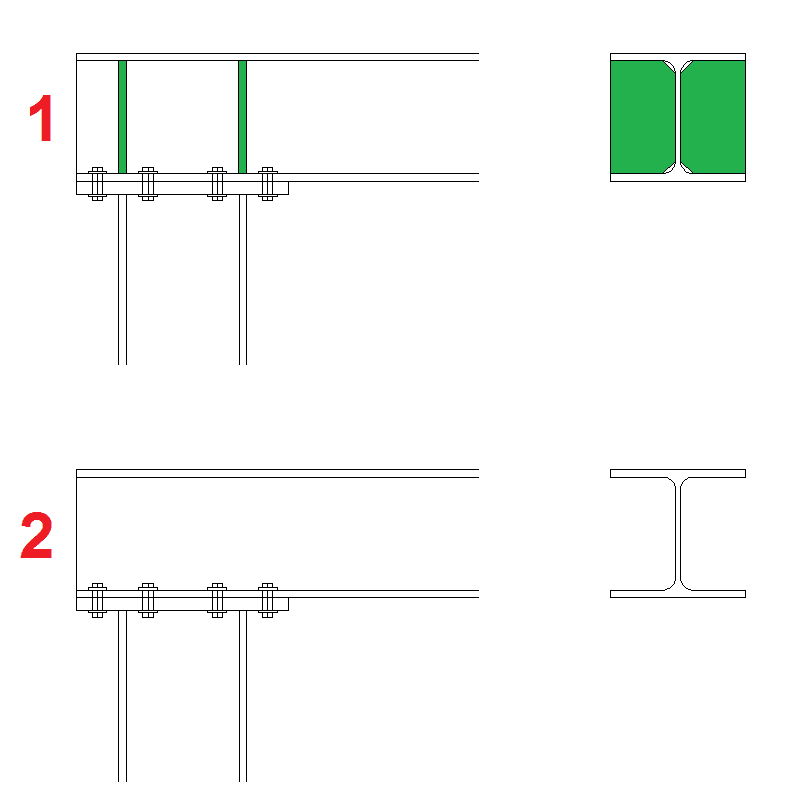
Im wondering do I have to make stiffeners in beam as shown in attached image (1) even tho web is stiff/strong enough and all controls are OK?
Im asking if my connection will be less stiff / rigid if I dont add stiffeners?

thanks for help
mc_xvqve2.png


moment_connection_t2iw7q.png
 
Replies continue below

Recommended for you

These stiffeners added when you make local checks on web and flange and checks are not safe if they are ok no need to add stiffeners. so in my opinion no big effect for stiffeners on rigidity of the connection.
 
depends on forces and stress if stiffener are needed or not...
but I would put some in anyway....
 
Fairly new at this structural engineering thing but, as far as I understand it, in order to achieve a FULLY rigid connection in practice, and thus satisfy the assumption as per your design model, you should have both flanges connected substantially to the column (i.e. tension flange of the beam should be able to transfer the tension force into the tension flange of the column).

With this in mind, the arrangement you show in your sketch, especially without the stiffener does not look very rigid to me. While it might work OK at ULS, you might find that the frame deflects / vibrates more than expected when loaded in practice. The stiffeners would make the connection a bit better (but I still wouldn't classify it as a fully rigid moment connection).

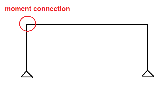
Typical connection for this application look like the below:
beam_with_mini_haunch_nes61l.png


I would wait for more experienced structural engineers on the forum to comment though :)
 
The connection you showed in the post could meet resistance with respect to the design moment (if you are not working with seismic requirements).

The question is: Are you sure that it guarantees good rotational stiffness? We evaluate that through Idea Connection (a finite element software that allows you to calculate the rigidity of the connections). For a connection of that type, I recommend that you include in the model the rigidity of the connection ... if you want to use it. The truth is that I do not like it very much ... but you choose...

 
- This would depend on the scale of the system for me. If this is keeping a main building diaphragm from flopping over, I'd definitely add the stiffeners. If it's somebody's trellis support, I'd probably be willing to do without.

- As others have mentioned, stiffness of the connection is one of the big issues here. You want some or you'll be inviting lousy serviceability and/or P-delta failure. Unfortunately, without resorting to FEM or testing of systems with adequate similitude, the joint stiffness is a difficult thing to estimate. This, largely, is what leads many a good engineer to just put the stiffeners in for good measure I think.

- Your beam needs to be braced against rollover at the beam column joint. And, without kickers or stiffeners, that's another difficult demand to quantify. For this reason alone, I'd almost certainly introduce a single stiffener into a frame like this if the frame was doing any serious work. And, of course, a single stiffener's bound to look goofy so I'd just do the pair over the column flanges and feel good that all was once again right with the universe.
 
I believe Eurocode has a methodology/equirements for the evaluation of joint stiffness. This includes stiffened and unstiffened configurations.

Refer to clause 6.3 of EN 1993-1-8 specifically, its just a matter of working through the equations given, though I've never done the calculations myself. It's the only method documented that I know of to determine an actual joint stiffness for different configurations without going down the FEM route. It should give you a good feel for the difference between a stiffened and unstiffened configuration.
 
If you send to me the plan of this connection, I will try (if work tasks allow me) to calculate this stiffness by FEM. (I think I can do it on Friday).
 
An extended bolted end plate connection (which is what the OP showed) is considered (by AISC at least) to be a fully restrained moment connection.
 
That is an interesting point JP. Any chance that you can tell us where AISC states that? I don't, for a second, doubt the voracity of your claim. I'd just like to check out the goods for my own edification and future reference.
 
KootK,

Design Guide #4, 2nd paragraph in Chpater 1 (1.1 background).

"The three extended end-plate configurations shown in Figure 1.1 have been tested for use in seismic applications. The intent of this edition of the Guide is to present complete design procedures and examples of the three moment end-plate configurations, which have been shown to be suitable for full constrained (FR or Type I) construction in seismic applications."

Bolding by me.
 
I've analysed a vertical end plate connection in Idea Statica in the past. An end plate without stiffeners is classified as "semi-rigid" (about 50% between pinned and rigid). Web stiffeners was enough to push the connection to "rigid".
 
Do simple elastic analysis with the following parameters -
1. Compression force is at the inner column flange
2. Tension force is at the outermost bolt row
3. Assign a tributary width to this bolt equal to the pitch of the bolts to get a design strip.

Now check this strip for deflection as if it were a cantilever beam against service loads. This is a quick easy way to check an upper limit for the rotation of the connection under the loads you'll see. Anything more detailed than this and your client is better served with the $1000 stiffeners than the $1000 science project.
 
bhiggins, We also did the calculation in Idea Connection.
I wanted to confirm it with this connection and send the results ... but that will be the result

[thumbsup2]
 
Status
Not open for further replies.

Part and Inventory Search

Sponsor