Enable
Structural
- Jan 15, 2021
- 788
This is an extension of this thread where I was called in to see if we could fast-track some lintels above the windows. Obviously that did not occur and we are now fashioning a system to remove the glass block in its entirety and in-fill with CFS.
Framing System of Work Area
0. Single story school (approx 3.7m or 12 feet) with pinned columns spaced at 5.3m (17 feet)
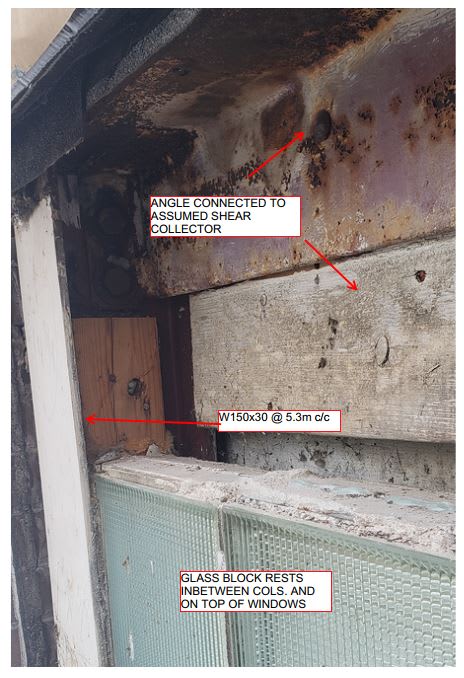
1. Steel W150x30(W6x20) columns have their strong-axis oriented perpendicular to windows / wall plane
2. Steel angle 150x150x6.4 (6x6x1/4) connecting week axis of columns at top. Seems to be riveted into adjacent 2x member behind. Seems like the 2x member collects shear from the roof diaphragm and distributes to the angle which then puts it into the weak axis of the columns
3. Roof decking is old style planks on angled direction across joists
4. Roof joists run parallel with the exterior wall. What those joists frame into is unconfirmed.
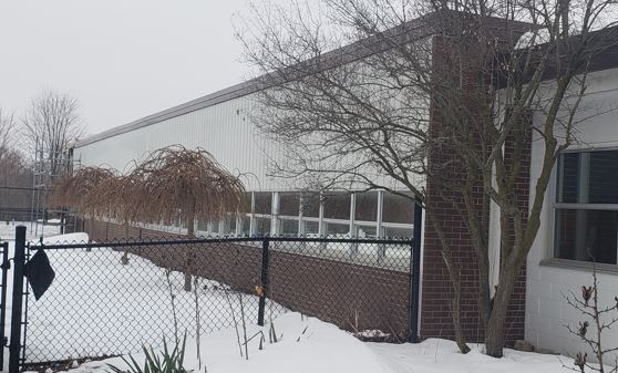
Exterior View
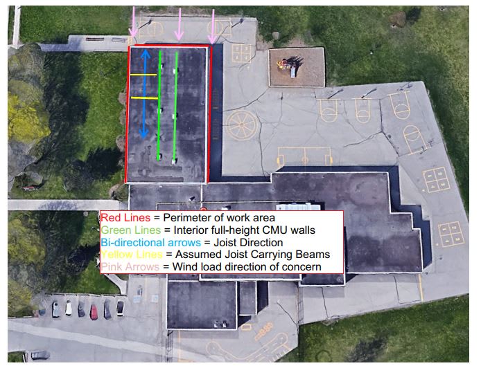
General Framing Scheme
Angle Connection
Problems I have
1. I don't see a true lateral system on the exterior walls and I'm fairly confident the roof diaphragm would be considered flexible (angled plank on 2x12 members) so the load is going to the exterior framing system (based on trib area) and into the ground...somehow. Right now I'm thinking there is just such a mass with the glass-block infill (it's almost the entire top half of the column) that inadvertently it's helping resist the lateral forces. So by taking it out I would making these columns cantilevers (more or less since but of course the angle would help some) which will increase deflection in the weak-axis considerably
2. Whatever solution we come up with cannot induce too much of a different load path else things start moving / cracking since all existing finishes are more or less staying
3. I'm hoping someone is just going to tell me I have missed the obvious here and DUH there is a system as is or that the CMU walls are likely hogging everything so not to worry
Solutions (??) I have
1. Create a weak-axis moment frame at the top of the columns to recreate the lateral stiffness of the block as much as I can
2. Place a pin-connected HSS member lower down above the window to pickup the CFS infill just above the new window location
3. My preliminary connection thoughts are attached. I'm rather concerned about inducing bi-directional moment capacity at my top connection. Ideally I want to avoid doing that and have a moment frame in the weak axis of the W-column only...don't know how possible that is. If you look at my sketch I think on the moment connection I have with a top plate / angle underneath might work well if I shorten the plate to within the confines of the HSS considerably (e.g. maybe a 3" wide plate but thickeer)
4. Key is to also think of fitup. We need to provide quite a bit of tolerance for the installer / erector given things will be totally baffed / out of plumb / whatever and they cannot be expected to line up holes to within 1/16" here
Misc Questions
1. I was going to place CFS infill on top of the HSS and use some powder actuated fasteners to hold it down. But this will puncture the HSS. How worried do I need to be about creating these holes given that the HSS is on an exterior wall and capped both sides? Any concerns about moisture / water infiltration / etc (assume there is a good water barrier on the exterior sheathing at least initially)?
Load information
1. Equivalent inplane lateral wind point load at top of moment frame of 10kN (2.3 kips)
2. Moment demand (assuming a moment frame) at top connection in weak axis of column of approx 6kN*m (4.4 kips*ft)
3. Vertical loads on HSS framing members (self-dead load only for the most part. Some infill CFS but nothing to get riled up about)
Framing System of Work Area
0. Single story school (approx 3.7m or 12 feet) with pinned columns spaced at 5.3m (17 feet)
1. Steel W150x30(W6x20) columns have their strong-axis oriented perpendicular to windows / wall plane
2. Steel angle 150x150x6.4 (6x6x1/4) connecting week axis of columns at top. Seems to be riveted into adjacent 2x member behind. Seems like the 2x member collects shear from the roof diaphragm and distributes to the angle which then puts it into the weak axis of the columns
3. Roof decking is old style planks on angled direction across joists
4. Roof joists run parallel with the exterior wall. What those joists frame into is unconfirmed.
Exterior View
General Framing Scheme
Angle Connection
Problems I have
1. I don't see a true lateral system on the exterior walls and I'm fairly confident the roof diaphragm would be considered flexible (angled plank on 2x12 members) so the load is going to the exterior framing system (based on trib area) and into the ground...somehow. Right now I'm thinking there is just such a mass with the glass-block infill (it's almost the entire top half of the column) that inadvertently it's helping resist the lateral forces. So by taking it out I would making these columns cantilevers (more or less since but of course the angle would help some) which will increase deflection in the weak-axis considerably
2. Whatever solution we come up with cannot induce too much of a different load path else things start moving / cracking since all existing finishes are more or less staying
3. I'm hoping someone is just going to tell me I have missed the obvious here and DUH there is a system as is or that the CMU walls are likely hogging everything so not to worry
Solutions (??) I have
1. Create a weak-axis moment frame at the top of the columns to recreate the lateral stiffness of the block as much as I can
2. Place a pin-connected HSS member lower down above the window to pickup the CFS infill just above the new window location
3. My preliminary connection thoughts are attached. I'm rather concerned about inducing bi-directional moment capacity at my top connection. Ideally I want to avoid doing that and have a moment frame in the weak axis of the W-column only...don't know how possible that is. If you look at my sketch I think on the moment connection I have with a top plate / angle underneath might work well if I shorten the plate to within the confines of the HSS considerably (e.g. maybe a 3" wide plate but thickeer)
4. Key is to also think of fitup. We need to provide quite a bit of tolerance for the installer / erector given things will be totally baffed / out of plumb / whatever and they cannot be expected to line up holes to within 1/16" here
Misc Questions
1. I was going to place CFS infill on top of the HSS and use some powder actuated fasteners to hold it down. But this will puncture the HSS. How worried do I need to be about creating these holes given that the HSS is on an exterior wall and capped both sides? Any concerns about moisture / water infiltration / etc (assume there is a good water barrier on the exterior sheathing at least initially)?
Load information
1. Equivalent inplane lateral wind point load at top of moment frame of 10kN (2.3 kips)
2. Moment demand (assuming a moment frame) at top connection in weak axis of column of approx 6kN*m (4.4 kips*ft)
3. Vertical loads on HSS framing members (self-dead load only for the most part. Some infill CFS but nothing to get riled up about)
