Continue to Site

Eng-Tips is the largest engineering community on the Internet

Intelligent Work Forums for Engineering Professionals

  • Congratulations KootK on being selected by the Eng-Tips community for having the most helpful posts in the forums last week. Way to Go!

Steel Perpendicular Connection

Status
Not open for further replies.

francis_intano

Structural
Sep 29, 2021
17
Does anybody know what this type of connections are called? Any references on how to design them?
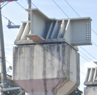
Perpendicular_Connection_fassog.png


I have a pretty much same structure to design, so I was thinking maybe I could do this scheme too. Any one who has an idea?
 
Replies continue below

Recommended for you

If you have to ask then you shouldn't be asking.

This applies whether you are a student (this forum isn't for student projects) or an engineer.
 
It's a heavy welded node on top of a concrete pedestal. This is likely a bridge application, where a specific firm will have designed it, in coordination with a fabricator, to a very specific set of loads/codes/requirements. Those huge stiffeners and bearing elements are there for a reason, perhaps seismic.

I don't know the reason, but you definitely need to know why. Start asking questions to your offline peers/leaders first, because a generalized answer from the internet can only take you so far with such a complex arrangement of specialized conditions, heavy welds, and stub beams. For instance, your geographic location alone could validate/invalidate the applicability of anyone's response from this site.
 
@ francis
connection between Steel and Concrete
attached file may be helpful
Link
 
It looks like a steel bearing connection of a bridge steel bridge onto a concrete column.

I'm not really a bridge design guy. But, this connection seems pretty unusual to me. I'd be wary to copy this unless you're getting some advice from an engineer with a lot more bridge design experience.

My guess is that this is NOT the most economical connection / construction. But again, I'm not much of a bridge guy.
 
Looks like a distribution platform for a bridge bearing carrying a very heavy load, probably in the thousands of kips. Given the small dimensions of the column, I would surmise the bearing it is to support is a sliding bearing or a seismic isolator.

In any case, as others have said, you shouldn't be copying the configuration for a different application. This is obviously designed for a very specific loading scheme.

Rod Smith, P.E., The artist formerly known as HotRod10
 
This looks like a one off design to me, so I doubt you will find a cookbook method to design whatever it is. What is your structure and what is the structure in the photo?
 
Thanks everyone! On another look, seems like a specialized design for specific project that I might inquire here locally.
 
Status
Not open for further replies.

Part and Inventory Search

Sponsor