Continue to Site

Eng-Tips is the largest engineering community on the Internet

Intelligent Work Forums for Engineering Professionals

  • Congratulations KootK on being selected by the Eng-Tips community for having the most helpful posts in the forums last week. Way to Go!

Steel plate design 7

Status
Not open for further replies.

frank28

Structural
Jan 14, 2019
11
Hello guys,

I need your help regarding with the steel plate design which I have never done before. I tryed to use Roarks book to find formula for my case but seems like there is no my case in his book so i used an other simple program that I also found here on thread. I compared the program results with the results I got from simple case from Roarks book and it seemed like its working fine. So in the file attached you can see my case with those results and give me your feedback regarding my calculations. I dont know if i have got this design good but it seems good for me. Also I need to design bolts together with the washers that are actually support for this plate and I wondering how. Any ideas / help? Thank you in advance.
 
 https://files.engineering.com/getfile.aspx?folder=30590af9-5260-4adf-aff6-893b9015958a&file=IMG_20190117_122433.jpg
Replies continue below

Recommended for you

Looks like the perfect problem for a yield line analysis. If you're unfamiliar with the process, the thread linked below is a good start.

thread507-210553
 
I'd probably just model it as a simple grillage or use shell elements. You could also use yield line theory as well as mentioned - personally I'd probably treat it is a flat slab type and use the standard equations to work out the proportion of moments in hogging/sagging regions (I've never really used yield line theory).

Be careful if you assume rigid supports it doesnt take much slip for one of the supports to do not do very much. Similarly if theres any rotation of the sling hook then one of the lines of supports will take more load than another.

Keep everything very robust IMO.

Also personal opinion not the cleverest weld detail for the sling hook although I acknowledge the stiffener is in the way (I think unless theres a pair of them)?. I'd rather it go through the plate and weld the other side, so the weld is then in compression but thats just me.
 
Many thanks guys im working according to british standards, even though standrard are the last thing on earth that is concerning me, my main problem is that I didnt understand this i was just guessing. Other thing, when me talk about bolts position, bolts that are support for this plate, in your opinion is it better to put the on the middle of the plate sides since that way they will some how in my mind prevent deflection more than if i put them in the corner of the plate more further from the place where force is acting? Thank you for suggestions i will go through what you have written and see if i can get any solution.
Kind regards.

Edit:

I went through the yield lines examples and some theory and it seems pretty straight forward so i guess i will use this to get moments in the middle of the span and on the supports as well which are going to be acting moments on plate, but than im having a question how to determine the plate resistance? Since im getting moment not stresses i cant compared it with fy, and to get resisting moment i guess i need effective width which brings me to begining.

Other thing, someone was talking about sling hook detail and there was a hole with the weld detail on the upper side of the plate metnioned, to keep weld in compression. That Kind of detail requirres cutting the hole in the plate which I guess does some damage to the bearing capacities of plate. If i do so, what Kind of restrictions i have to take in account while designing the plate? Also there was a suggestion from clients to weld sling hook into one smaller plate and than weld that smaller plate o to this one, but the smaller plate in my opinion seems unusefull.
 
This problem is statically determinate. Accordingly, yield line theory is not needed to solve it.

The span is 190 mm in each direction, so the plate can fail by a single fold line at the midspan. The fold line can be parallel to either X or Y axis. The moment is PL/4 and the fiber stress in the plate is PL/4S where S is the section modulus, bt^2/6. So fb = 6PL/4bt^2

If t = 10mm and b = 190, fb = 6*7,250*190/(4*190)10^2 = 108.75 MPa

Actually, b > 190 (not dimensioned on sketch) so assume b = 25 + 190 + 25 = 240mm

Then fb = 86.1 MPa

frank28 said:
in your opinion is it better to put the [hangers] on the middle of the plate sides since that way they will some how in my mind prevent deflection more than if i put them in the corner of the plate more further from the place where force is acting?

Yes, it is better. The span is reduced and b is increased. But if you are going to do that, you could simply use a smaller plate and rotate it 45 degrees.


BA
 
I didn't see your edit. Why not drill a hole in the middle of the plate and use a sling hook with threaded end and nut above the plate similar to the four hanger rods?

I agree that adding another plate seems like an unnecessary step.

frank28 said:
That Kind of detail requires cutting the hole in the plate which I guess does some damage to the bearing capacities of plate. If i do so, what Kind of restrictions i have to take in account while designing the plate?

The hole should be drilled (not cut). The 'b' dimension of the plate is reduced by the diameter of the hole.

BA
 
Many thanks guys you've helped me a lot all of you and I now understand what I'm doing. One last thing, I suppose I have to use some of failure mode to design distances of hangers from edges, but which one and how do I do that?
 
Would also add, agree I would tack on a dynamic factor, magnitude depending on the context/loading of the sling hook
 
Loading is static so I guess no need for that.

Update I can't drill a hole through the plate due the some special clients request so I am going with this fillet weld. Hope it won't collapse :D
 
frank28 said:
One last thing, I suppose I have to use some of failure mode to design distances of hangers from edges, but which one and how do I do that?

Nothing special. Just use the normal edge distance for the diameter of the hanger rods.

frank28 said:
Update I can't drill a hole through the plate due the some special clients request so I am going with this fillet weld. Hope it won't collapse :D

The fillet weld is a bad detail. If the load is not directly under the hook, there will be bending as well as tension. Hoping it won't collapse is not very reassuring; you need a better detail.

It is not clear why you are using this assembly at all. Why not fasten the lifting hook directly to the crane instead of using a plate?

BA
 
...not the same but similar

bilancino_TTGC_01_de8mli.jpg
 
Ok guys, I am not really sure why does it have to be this way but I was just told to do so. Anyway I will try to give more than one solution to this problem so the first extra solution with this that you say it wont work is going to be the one with the hole in the middle of the plate. I am attaching you a skatch to confirm that I got you correctly. Is this what you had on your mind?
 
 https://files.engineering.com/getfile.aspx?folder=0a2c9eb8-11e5-4a06-b4cb-da998bc6f2f6&file=IMG_20190121_120150_BURST002.jpg
plus thick washers and double-nuts everywhere.
PS : when I calculate something like this I keep in account only 3 rods (and nor 4) because the 4th one probably is not working or not working same as the other 3
 
Why is that case with the one not working?

How does the hole affects yield line calculation?
 
3 instead of 4 : (same design I use in a press with 4 columns). To set a flat plane are enough 3 points (Euclide's geometry): the 4th must lay on the plane, but in the mechanical world you have tolerances, so , most likely, the 4th point is never exactly on the plane. This assumption only for the design of the 4 rods, not the plate.
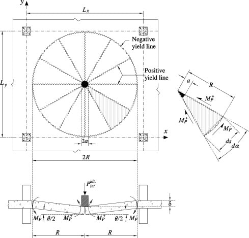
To keep in account the central hole you can refer to "yield line analysis of rectangular slabs with central openings" - Zaslavsky - J. ACI, vol 64, no. 12, 1967, pp 838-844 (or, more simply, considering the real length of the yield line)
 
robyengIT said:
but following scheme is better

That solution may be okay for a slab panel on columns which are prevented from moving laterally by slab panels all around the one in question but it is completely wrong for the case at hand and leads to extremely unsafe results.

Yield line analysis may be used for this case but it is not necessary as the critical failure mechanism can be readily seen by inspection. In the case at hand, the hanger bolts provide neither lateral resistance nor moment resistance. Failure occurs when the plate folds at midspan and can occur in either of two ways. The fold line may be parallel to either X or Y axis.

M = PL/4 where P is the load and M is the bending resistance required of the plate. If the width of plate is b, the section modulus is bt^2/6 and the maximum fiber stress is 1.5PL/bt^2.

The factored moment capacity of the plate is φFy*Z or φFy*bt^2/4 where Z is the plastic modulus and φ is a resistance factor, normally taken as 0.9 for steel in flexure.

If the plate has a hole of diameter d at midspan, use (b-d) instead of b in the above formulas.

BA
 
Guys you're golden. Can't figure out the way to show hoy thankfull I am.
 
The little purple star (lps) under each post allows you to express appreciation.
 
Status
Not open for further replies.

Part and Inventory Search

Sponsor