Continue to Site

Eng-Tips is the largest engineering community on the Internet

Intelligent Work Forums for Engineering Professionals

  • Congratulations KootK on being selected by the Eng-Tips community for having the most helpful posts in the forums last week. Way to Go!

steel retrofitting to a water tank 1

Status
Not open for further replies.

Yazan Atoum

Structural
Nov 4, 2016
18
Hi guys,

I have a water tank with a depth of 4 meter and planar dimensions of 9X4 meter squared

the problem when it is filled with recycled water to a depth of 3.5 m, what happened in reality that the tank bloat and the walls tend to bend to the outside, I am thinking of a retrofitting method, which is using steel beams to brace the tank from the inside at two levels , all connections will be hinged and no weld to be used for corrosion prevention purposes.
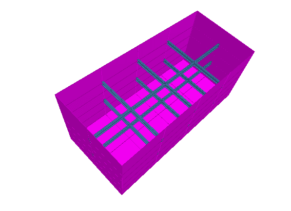
Capture_emsnxk.png

I check the beams for tension and the plate for von mises stresses

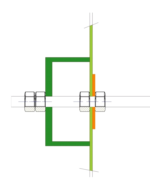
I thought of using IPE200 beams screwed to the water tank walls with double angles, the screw is similar to what is used in sheet to purlins connection, I think the bolts should be qalvanized and a special material should be applied to prevent any leakage from the holes.
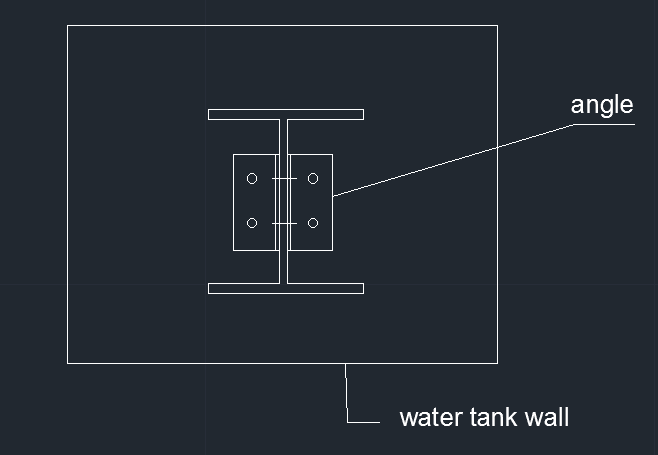
wwwww_m748ot.png


I am worried about what i came with, do you have any concerens or shall I proceed?
 
Replies continue below

Recommended for you

The material of the tank is steel plate with 6 mm thickness. and the water in not potable.
 
how can the bm to the sidewalls be in shear?....perhaps the OP meant tension.....
 
if possible, it would be more effective to to run a horiz stiffener/bm on the outside where the internal braces connect to the walls.....
 
External full perimeter stiffening elements would be the more conventional way to do this. Run angles, horizontal plates, or WT members continuously around the tank perimeter at whatever vertical spacing you need to hit your deflection target. Alternately, you run a perimeter stiffener along the top and bottom, and then span vertical stiffening elements between them. You can add ties between the top beams on opposite sides if you want.

There's two major problems with what you've proposed. You've created big stress concentrations at the points where the tie beams connect to the tank wall, which is problematic with plate walls. On top of that, the bolted connections will be a reliability nightmare.
 
The proposed beams are acting as tie-rods. If you are going to drill holes in the walls of the tank, just use rods instead of beams and thread the ends.
As mentioned, stiffeners on the outside of the tank are the usual approach.
 
So everyone also agrees that welding from the inside will be problematic as it will corrode, if not this will be the easier option.

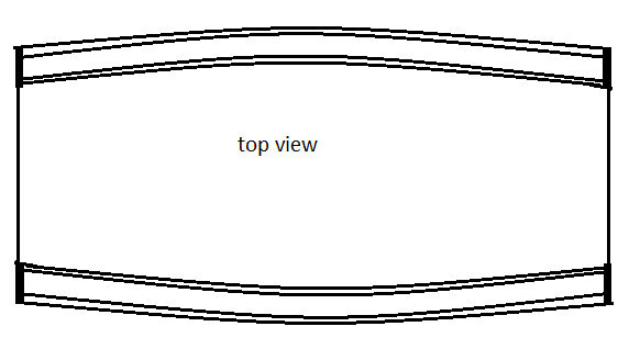
The problem is that when beams at two levels were welded at the exterior face of the tank, it didn't solve the problem and the water load bent the beams to the outside. This is an actual problem happened in reality, noting that the supporting beams were only connected to the tank wall at the corners.

1212_cue0og.png
 
Before you go to all the analysis and expense of trying to make this sow's ear into a silk purse, you might want to check out the price of a round steel, HDPE or FRP tank. You're talking about a 35,000 gallon tank. They're off the shelf items.
I've chased these designs and they're very difficult to get right. The stiffeners are tearing at the welds, the plates are bending in two direction, and every time you uncover something, you've got to stiffen something else.
 
So everyone also agrees that welding from the inside will be problematic as it will corrode, if not this will be the easier option.
Not necessarily. If you weld the entire circumference of an open profile (WF, C-channel, ...) in a correct way, there will be no problem. Bolted connections, drilling holes through the wall, single-sided welds, ... are all asking for trouble.

Or follow the very sound advice from JedClampett.
 

The water will be filled with oxygen for recycling, I don't really know the process of water filtration, but the condition will be a bit harsh on the weld, that made me excluding it as it cannot be guaranteed.

I agree with JedClampet, the evaluation of such structures is not a straightforward process.
 
If a 6mm steel tank can survive the environment, I fail to see why the weld wouldn't.
 
Clearly the beams were too weak, or the deflection criteria too tight. Beams on the outside per TLHS are the way to go, or JedClampett's suggestion. The design of rectangular bis is not rocket science, there are several good technical references out there. You can also consider angle braces on the inside with repads to the shell and bottom - the liquid pressure on the bottom anchors the brace and it resists the hydrostatic pressure on the wall. The wall will never remain straight and flat but that is OK as long as it does not become overstressed. This one is small in the grand scheme of things.
 
It's not particularly complicated.

You design the wall to span between stiffeners. You design the stiffeners to span between carrying beams and design the carrying beams to span between tension ties.

If you want tension ties only, you have several significant problems to overcome. I'm guessing you will have 20,000# of tension as you have it cartooned. Not appropriate for screws. To make the forces manageable you will need those tension ties every couple of feet in each direction. Maybe a whole mess of rods as CompositePro suggests. You could probably install a bearing plate on the outside where the rods bear and do some kind of two-way analysis on the plate. You didn't mention the plate composition or thickness.

Regardless, water tanks 4 meters deep make for some big forces. One should not just guess as to the details of these kinds of tanks.

 
Yazan Atoum said:
The problem is that when beams at two levels were welded at the exterior face of the tank, it didn't solve the problem and the water load bent the beams to the outside. This is an actual problem happened in reality, noting that the supporting beams were only connected to the tank wall at the corners.

Why would you only attach it at the corners? You lose all composite action doing it that way, and will significantly affect the ability of the retrofit to control deflection?

Also, for something like this it's definitely economical to continue the stiffeners around to the short ends and do a moment connection at the corner to reduce rotation there as well.

 
Good information above.
It is not common to build rectangular tanks, due to the added weight and labor as compared to a round tank.
If built, there is no set way to detail it and no standard for design.
Stiffeners can run vertically or horizontally or both as desired.
Stiffeners welded continuously to the walls can be designed as composite sections including a portion of the wall plate.
The walls will frequently fall into the large-deflection category of bending which complicates the design.
It will often be advantageous to arrange the stiffeners to make the design simpler, even where a more complicated design might produce a slightly cheaper tank.
The deflections you mention might be the intended design- hard to say without seeing the numbers and actual tank.
Internal stays would more commonly be rods than structural members, for ease of painting, etc.
Note that you may get high bending stresses in the plate at the stays.
Internal stays clutter up the interior, making it harder to perform work in there.
 
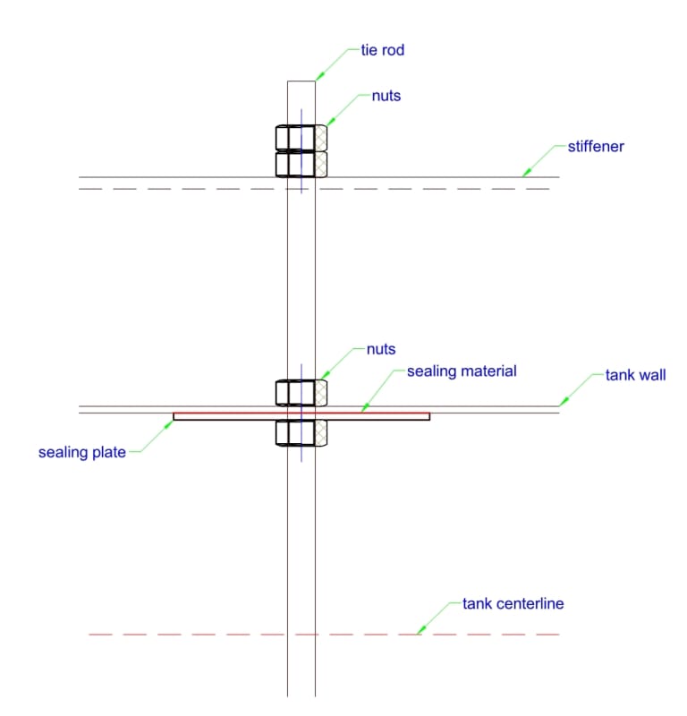
without any calculation, only a suggestion but no welds (i.e. tie-rods threaded at both ends, stiffener as U-channel)

tank_tie_rod1_jkqz5w.jpg
 
Status
Not open for further replies.

Part and Inventory Search

Sponsor