Continue to Site

Eng-Tips is the largest engineering community on the Internet

Intelligent Work Forums for Engineering Professionals

  • Congratulations KootK on being selected by the Eng-Tips community for having the most helpful posts in the forums last week. Way to Go!

Steel Sleeve Around Bearing 4

SwaggingIt

Mechanical
Oct 31, 2014
22
I'm working on a flight controls actuator and since I'm fairly new to the arena I'm not familiar with best practices.

Theres been questions raised that a few of our highly loaded bearings (towards the flight surface output) should have steel sleeves around them because they are in aluminum housing. I understand that this might potentially mitigate thermal and aluminum housing wear, but I was really hoping to get more experienced people to chime in with their opinions or what kind of analyses they run to determine the necessity of the steel sleeves.

Space is tight in the actuator so adding these sleeves wont be easy. Plus, the steel sleeves need to be press fit into the aluminum housing, and then the sleeve ID needs to be machined to match the bearing OD, so this is adding extra process too.

Very grateful for any advice/opinions. I take everything with a grain of salt so please dont hesitate to offer any suggestions.
 
Replies continue below

Recommended for you

Its all about durability/ wear under fatigue loads. Hard to analyze. Hence why companies have design rules and guildelines.

Every aerospace fitting that I have seen that has a pin joint for moveable attachments has bushings in every hole. Typically steel or nickel-bronze. Those bushings provide a durable wear surface and are replaceable in service. You don’t want an operator having to replace the entire bolted in fitting.

Yes, the fab process is more expensive. Too bad. The consequences of wear and failure are too high.
 
Thanks for the feedback.
To provide some more clarity, its a geared actuator with mostly radial ball bearings. Its these radial bearings that are in aluminum housings that I'm asking about.

Just wondering if other have had the same situation, what drove them to the decision they made about adding or not adding a steel sleeve around the bearing.
 
Run a fatigue durability test with and without a sleeve, and let real data guide you.

Do you really want to put a durability problem into service?
 
The analysis that I have seen done is failure analysis when the bearing wallowed out the aluminum bores. Even small amounts of relative motion lead to fretting wear that allows clearance to increase, which leads to more movement, more fretting, more clearance.

Similar to not doing analysis about passivating corrosion resisting steel or using alodine/conversion coat on aluminum before painting, the observation of what happens with no sleeve is enough.
 
There are some models that cover fretting fatigue and abrasive or adhesive wear. I'd have a look through some of the classics. I have done these type of calculations to inform inspection requirements/schedules for pin/bushing interfaces before.

A good reference is Robert Norton's "Machine Design: An Integrated Approach", specifically chapter 7. Based on the materials, applied force, contact area (maybe the trickiest to compute, you might need a Hertzian contact analysis), etc. you can predict the depth of wear. This can inform a basic understanding of how many load applications are tolerable but it's a bit iterative because the contact area will change as material is worn away.

2024-11-14_17-17-29.jpg

2024-11-14_17-17-46.jpg
 
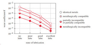
@LD ... something about that graph (of K) seems odd unless the other factors mitigate ... ok, so K decreases with Lub ... makes sense ...
but why is wear for incompatible metals 100 times less that identical materials (at the same lub assumption) ?

is the legend flipped ?
 
What makes you say none of us understand the configuration?
Well,

The OP mentioned an aluminum housing, and later stated that it's a radial ball bearing.

You offered a formula to calculate wear of the race the balls are running on. I hope that's not aluminum.

@3DDave and I are imagining a ball bearing assembly pressed into an aluminum housing.

@SWComposites is imagining a pin and bushing.

We're all filling in the gaps with our own imaginations because the OP's description is vague.
 
My apologies. I can see where that might be confusing. We work exclusively with steel bearings so I forgot to consider the other possibilities.
52100 bearing material, 1" OD, 0.28" width. The entire bearing is seated in a housing that is aluminum.

What 3DDave and LiftDivergence said resonate a lot and is the kind of information I was hoping for. Thank you!
 
FYI...

General retained-bearing installation practices... choose your bearing wisely...
AIA/NAS NAS0331 BEARING INSTALLATION AND RETENTION BY SWAGING OR STAKING

IF a sleeve is 'really' needed...
AIA/NAS NAS0332 BEARING RETENTION SLEEVE, GROOVED OUTER FACE

Good stuff...
MIL-HDBK-1599 BEARINGS, CONTROL SYSTEM COMPONENTS, AND ASSOCIATED HARDWARE USED IN THE DESIGN AND CONSTRUCTION OF AEROSPACE MECHANICAL SYSTEMS AND SUBSYSTEMS

SAE ARP5770 Design Guidelines for Aircraft Mechanical Control Systems and Components

Remember one rule of thumb.

Plain bearings... like bushes... are usually installed in light/medium interference... then ID reamed-to-size.

Anti-friction bearings [ball, roller, etc], should be installed with a slight clearance-down-to-a-net-'0zero'-fit. Any interference may 'squeeze-out' the designed internal clearances and affect bearing resistance/wear.

OH... and never forget added corrosion protection [isolation] between the outer-race of a bushing or bearing and the mating hole.
 
Last edited:
FYI...

General retained-bearing installation practices... choose your bearing wisely...
AIA/NAS NAS0331 BEARING INSTALLATION AND RETENTION BY SWAGING OR STAKING

IF a sleeve is 'really' needed...
AIA/NAS NAS0332 BEARING RETENTION SLEEVE, GROOVED OUTER FACE

Good stuff...
MIL-HDBK-1599 BEARINGS, CONTROL SYSTEM COMPONENTS, AND ASSOCIATED HARDWARE USED IN THE DESIGN AND CONSTRUCTION OF AEROSPACE MECHANICAL SYSTEMS AND SUBSYSTEMS

SAE ARP5770 Design Guidelines for Aircraft Mechanical Control Systems and Components
I saw one of your other posts on a similar topic and was going to reach out to you individually. This is great info and really appreciate your time to provide these standards. thank you!
Same goes to everyone else too. Thank you!
 
OP

all great theoretical information based on what works.

ball bearing are effected by many factors as set above and all great information.
now as actual practical pull a bearing from a 1980 or 1990 honda transmission , these transmission where generally bullet proof.
pull a bearing from the failures from a 1980 renault , not so good and high failure rate. unfortunate because it really had some great other designs.

the renault transmission had a relative thin race , and could easily great knocked out of round and the hole for the bearing had to be nearly perfect.
as mentioned above out rounds or over press can have bad results.
rigidity can make or break a design. contact stress, roundness, contact stress of all details. clearance and precision.
 
@LD ... something about that graph (of K) seems odd unless the other factors mitigate ... ok, so K decreases with Lub ... makes sense ...
but why is wear for incompatible metals 100 times less that identical materials (at the same lub assumption) ?

is the legend flipped ?
RB, the source of this graph is originally from Rabinowicz who "wrote the book" on wear, so to speak. The source of the figure from Norton is actually from the Wear Control Handbook by MB Peterson and Wo Winer. I have done some checking to make sure it is correct.

I think the thing to keep in mind is that this figure is specifically for adhesive wear from contact of parts. The wear coefficient here is associated with material loss. If the materials are metallurgically identical, deposition of material through adhesive wear in sliding contact, for example, will be "easier".

Your intuition I think is correct though because we generally tend to think of dissimilar materials as having different hardness which also has a big effect on wear. There is a separate parameter for hardness in the wear depth formula, the effects of which might have a bigger impact than the constant, K, I guess, depending on the materials.
 
Last edited:
Well,

The OP mentioned an aluminum housing, and later stated that it's a radial ball bearing.

You offered a formula to calculate wear of the race the balls are running on. I hope that's not aluminum.

@3DDave and I are imagining a ball bearing assembly pressed into an aluminum housing.

@SWComposites is imagining a pin and bushing.

We're all filling in the gaps with our own imaginations because the OP's description is vague.

Respectfully, I think I understand the problem. OP said:

"Plus, the steel sleeves need to be press fit into the aluminum housing, and then the sleeve ID needs to be machined to match the bearing OD, so this is adding extra process too."

He's saying the O/D of the bearing is set into an aluminum housing and he wants to know if there should be a steel sleeve press fit into the housing to act as a wear layer between the OML of the bearing outer race and the inner face of the hole in the housing.

Your statement:
You offered a formula to calculate wear of the race the balls are running on.
Not inherently, no. This is a general method for characterizing wear depth that is not specific to bearings or bearing races.
 
You eould not typically need a plain bushing to install a bearing into an aluminium fitting.

(Unless it's a swage sleeve? )
 

Part and Inventory Search

Sponsor