Eng-Tips is the largest engineering community on the Internet

Intelligent Work Forums for Engineering Professionals

  • Congratulations waross on being selected by the Tek-Tips community for having the most helpful posts in the forums last week. Way to Go!

Steel strap lightgage shear walls 1

Status
Not open for further replies.

MacGruber22

Structural
Jan 30, 2014
802
0
0
US
Getting into more serious lightgage design than I have done in the past. Attached is a sketch that shows tension straps welded to the shear wall double end posts (in reality the straps are configured as x-bracing, 4 straps total). I am concerned about a few things.

1. With a single-sided angle, the vertical component of the strap force has to pass through the inside stud to get to the angle. To me, the allowable tension capacity of the end post is limited to one stud. Our shear wall spreadsheet does not check this. Maybe there is good reason not to?
2. Our spreadsheet relies on the horiz. component of the strap force to be resisted by the track, but doesn't explicitly check it (!). My question is what unbraced length lengths should be used for this compression member with PAF's at some interval. Also, there has to be an AISI limit on the number of fasteners over a given length that can resist shear.

This single-sided angle detail seems to be the standard at our office, but my feeling is that two angles would greatly help out with my question number 1, in additional to prying on the embed (which also seems to be ignored). Part of me also, wants to provide standard holes in the angles (or weld the washers) and transmit the shear directly to the anchors, and ignore the track for in-plane loads.

"It is imperative Cunth doesn't get his hands on those codes."
 
 http://files.engineering.com/getfile.aspx?folder=fc4bb8f4-9c9f-4222-a443-c16304d4baa1&file=Lightgage_Sketch.pdf
Replies continue below

Recommended for you

1) Agree. Could alleviate with back to back studs.

2) I can see an argument for the distance between PAF's but initiating some kind of fastener pull through failure concerns me. I'd be inclined to use the stud spacing. I would expect a limit on the number of effective shear fasteners. Particularly given that the track won't be a single piece forever (10?).

These details address some of your issues: Link


I like to debate structural engineering theory -- a lot. If I challenge you on something, know that I'm doing so because I respect your opinion enough to either change it or adopt it.
 
Thanks, KootK. I like some of those details in your link, but I am trying to work within our company's detail - they don't like changing things.

Something about the design example doesn't make sense to me. The straps are tension only members. That should make the tension chord a zero force member from top to the location where the strap is connected.

"It is imperative Cunth doesn't get his hands on those codes."
 

Agreed. That doesn't change the design tension demand on the stud group however.

I like to debate structural engineering theory -- a lot. If I challenge you on something, know that I'm doing so because I respect your opinion enough to either change it or adopt it.
 
I recommend a more "concentric" detail--try to make the lines of action meet at a single point--where the center of the double stud intersects the concrete foundation wall.

You are correct about the double stud--it has zero force. But the double stud at the other end of the shear wall will have a large compression force. Since lateral load can occur in either direction, a double stud must be provided at each end of the shear wall.

DaveAtkins
 
Dave said:
I recommend a more "concentric" detail

I quite agree with this. Frankly, I have a hard time seeing the proposed detail passing muster save for the lightest of loadings. A partial list of issues would include:

- those already mentioned.
- weak axis bending of the stud pack.
- fastener tear out across the flanges of the stud pack members.
- stud flange crippling where the stud pack pushes against the angle.
- angle prying on the anchor bolt (common to many versions of the detail really).
- as far as I can see, no mechanism for transmitting brace tension to track/PAF shear.

While I appreciate the impetus to not instigate a bunch of fee burning change, this might represent an important opportunity to help your firm improve their product. Some of the details that are much better mechanically should be no less costly to construct in my estimation.


I like to debate structural engineering theory -- a lot. If I challenge you on something, know that I'm doing so because I respect your opinion enough to either change it or adopt it.
 
I usually attach the strap to an angle iron or channel bolted to the slab (MC6x18)
That takes all that nonsense out of the equation. Still got to check bolt pullout, shear and prying force, however.
 
KootK said:
- weak axis bending of the stud pack.

That is a major problem. I played around with the effects of the strap eccentricity by analyzing the real geometry in a general FEM program that can code check cold-formed sections. As expected, the minor axis bending prohibited a reasonable quantity/gage of studs.

KootK said:
- as far as I can see, no mechanism for transmitting brace tension to track/PAF shear.

Another major problem, other than two screws per stud to the the track, which would never do the work.

I also agree with the other items in your list. I also asked around the office about some of these things, and the typical answer was "I never checked that, I don't know, *shrug shoulders*".

KootK said:
this might represent an important opportunity to help your firm improve their product

I tend to try to do this when I notice something, but the resistance is always high and chock full of "we have always done it thing way". It has pushed me to just doing what is right for my projects and not worry about others.

XR250 said:
I usually attach the strap to an angle iron or channel bolted to the slab (MC6x18)

I follow for attaching the straps to the channel flanges, but I don't see how that works with the chord studs. Sketch, maybe?

"It is imperative Cunth doesn't get his hands on those codes."
 
MacGrubber22 said:
I tend to try to do this when I notice something, but the resistance is always high and chock full of "we have always done it thing way.

Just wait until you're management and you actually find yourself part of the inertial mass of mediocrity that keeps things from improving. It's the bestest.

MacGruber22 said:
I follow for attaching the straps to the channel flanges, but I don't see how that works with the chord studs. Sketch, maybe?

I believe that this is similar to your own point. For one story, there is not tension chord with XR's detail. Not even for the bottom 6" or whatever. Just diagonal tension strap and compression strut.

I like to debate structural engineering theory -- a lot. If I challenge you on something, know that I'm doing so because I respect your opinion enough to either change it or adopt it.
 
KootK said:
Just wait until you're management and you actually find yourself part of the inertial mass of mediocrity that keeps things from improving. It's the bestest.

I hear you.

KootK said:
I believe that this is similar to your own point.

I got it - for some reason I was imagining the studs nestled in the channel

KootK said:
Some of the details that are much better mechanically should be no less costly to construct in my estimation.

I forgot to mention that I like that simple argument.

"It is imperative Cunth doesn't get his hands on those codes."
 
In my office we use Simpson hold downs on both sides of the stud post. They have capacities for them welded or screwed to the post. The nice thing about them is the are 'predeflected' so any elongation, straining in the hold down has been forced into, so less building drift due to hold down deflection at least. We then distribute the load between built up posts by the welds between them near the strap. We have found when loads get large and the built up post gets to be (3) or more 14 ga or heavier studs, it is more economical to use 3/16" HSS members instead.

The track, as shown in the example, is easy to design for tension, as if the track 'behind' the shear wall grabs the shear force down its length. This is difficult to have in reality, and the track is very hard to design for the shear in compression, even assuming the distance from PAF to PAF is the unbraced length.
 
geoffdale, do you know what the $$? I would love to recommend a reputable software (to the higher ups) in lieu of a 15-year-old spreadsheet. We currently use CFS 9.0, LGBeamer v8, and AISIwin8 for our light gage stuff. But it is very odd to me, because we don't generally do full-scale light gage design. We mainly only provide gravity member sizes for pricing sets, and we design the lateral system.

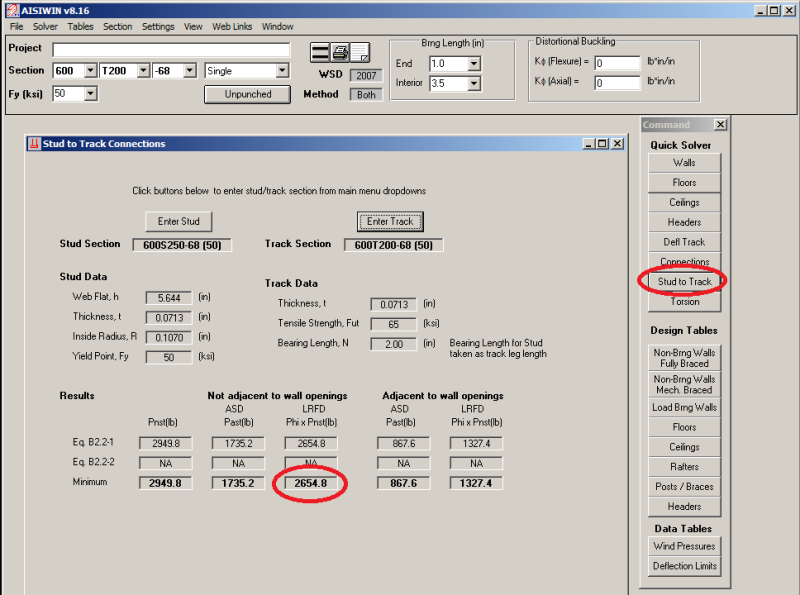
structSU10 - yes, our office has reference jobs where HSS posts were uses. In designing my first wall, I have noticed that the stud-to-track connection in compression is a problem even when uplift is taken by a hold-down device. From a double stud chord, 600S250-68 [50], and 68 mil track, I can only get 2.6 kips per stud in LRFD compression. That seems very limiting when trying to develop the full axial capacity of a double 600S250-68 stud weak-axis braced at 48" o/c.

structSU10 said:
We have found when loads get large and the built up post gets to be (3) or more 14 ga or heavier studs

I am assuming your increase in studs was because of the track compression connection?

If there is not a practical way to increase the stud-to-track crippling strength, adding more studs to the post group seems like a waste of time in a hurry. Maybe I need to add more shear wall segments or switch to tube posts.

A sketch in progress attached based on XR250's recommendation. As David mentioned, I am working on making a concentric detail for the top of the wall with the straps welded to a 3" deep distribution tube (drag strut).

"It is imperative Cunth doesn't get his hands on those codes."
 
 http://files.engineering.com/getfile.aspx?folder=32e21fb4-9f7c-4699-8792-5df4105ba25c&file=SKETCH.pdf
What is nice about the channel is than you can do a double sided strap which keeps things concentric on the compression studs. You could then use a 6x2 tube steel distribution member.
 
XR250,

You are proposing welding a channel section to the underside of the distribution tube too?

I am already using a 6x3 distribution tube for all of the load-bearing walls, so I was just going to replicate that at all shear walls and weld the straps directly to the tube. It gives me enough weld length, and it seems concentric enough - the center of the weld group aligns about at the inside face of the end post stud. I feel good about that tube uniformly compressing the post studs.

I am still mulling over what appears to be the Achilles heel of the system, the stud-to-track bearing.


"It is imperative Cunth doesn't get his hands on those codes."
 
MacGruber.

What I typically do is a 6x2 tube on top of the wall, an MC6x18 section at the bottom of the wall and a strap on each side. The double strap keeps from having out-of plane eccentric loads on the studs.
Stud to track bearing - are you talking about the gap that always exists between the two? Go do a few inspections and you will see how big it can really get.
I have stopped doing most light gage load bearing jobs. I just never see it getting built correctly. I imagine the interior and exterior sheetrock are what really brace these walls.

 
XR250 said:
Stud to track bearing - are you talking about the gap that always exists between the two?

Not exactly. I can imagine the problems with the construction, particularly if special inspections are not employed (I feel they need to be for the lateral force resisting systems). The AISI standards seem fairly clear about the problems when the gap is excessive, but I am really looking for guidance on how to get the end bearing capacity of the double 600S250-68 post to be much closer to the braced compression capacity of the stud group. Basically, with my current shear wall configuration, I need 28 kips of post-to-track bearing (or some other force transfer mechanism). I am leaning to "impossible/impractical". But again, I am not overly experienced in light gage design, so I may be overlooking at provision for built-up posts that significantly increases the groups bearing crippling capacity.

See the output below, it seems I am maxed out at 2.6 kips per stud (software doesn't have a module for built-up posts).

Currently, I am thinking about:
1. Switch back to a post hold-down that could also transfer compression? I looked at the Strong-tie hold-downs, but they are not rated for compression. Further, if I go back to that configuration, the shear needs to be resisted at the hold-down too. Not good.
2. Sketching to HSS chords
3. Reconfiguration my rigid diaphragm lateral load distribution in order to reduce the max chord compression to no more than 2x 2.6 kips.

Am I missing something here?

stud_to_track_yrcylk.png


"It is imperative Cunth doesn't get his hands on those codes."
 
I believe the 2.6k capacity indicated in the program output for the stud to track connection is for an out-of-plane end reaction of the stud to track (web crippling type load) not an axial bearing capacity.
 
WAMRE said:
I believe the 2.6k capacity indicated in the program output for the stud to track connection is for an out-of-plane end reaction of the stud to track (web crippling type load) not an axial bearing capacity.

I believe you are right! So does that mean there is no end of stud bearing check?

"It is imperative Cunth doesn't get his hands on those codes."
 
28k? Seriously? I would not be using LGS in that territory.
You actually can check a built-up stud in AISIWIN, but only two back to back or boxed.
I have never checked end bearing. The stud will fail in many other ways before that occurs.
The module you are using is for checking out-of-plane loads between the stud and the track, not end bearing.

 
Status
Not open for further replies.
Back
Top