Hello,
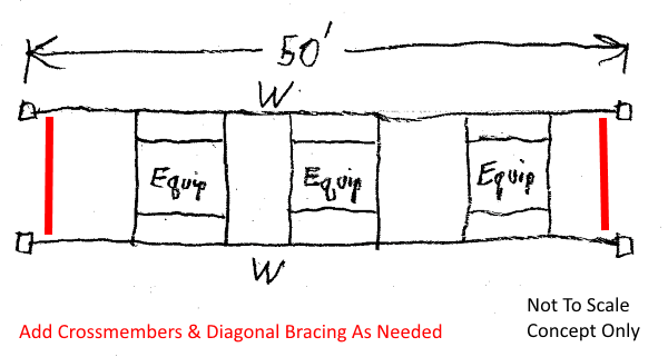
Please refer to the attachment. I am designing a support structure for three mechanical units to sit on it. The structure will span over the roof of a walk-in cooler and the units will be bolted directly to the W16x67 beams. I am thinking that these long beams will be connected to the columns with single plate shear connections to handle the shear and then have full penetration welds at the top and bottom flanges to resolve the moment. Does that connection sound like the best approach? Can the top flange weld be made to the column cap plate if the cap plate is sufficiently welded to the column?
I haven't figured out my wind and seismic loads just yet but hope to do so today. The structure will basically be constructed of two 50'-0" long moment frames. I am generally looking for advice on the best way to connect the two 50'-0" long frames together so the structure can resist lateral loads transverse to the 50' frames. I will ask specific questions below:
1. What is the best way to connect the columns together as shown in "ELV. 2" to create a 7'-0" long frame transverse to the 50' frames? Should I just put a beam at the top and design it for moment connections, or is "X"-bracing with angles or rods a better design? There will be no gravity loads that need supported at this location.
2. What is the best way to connect the two 50'-0" long beams together in order to get transverse loads over to the two 7'-0" long frames? Should I use angles welded to the underside of the top flanges at approximately 45 degree angles like my sketch shows?
3. If I do connect the 50'-0" long beams together as I propose in question #2 above, would it be appropriate to design the beam with the compression flange braced at those intervals? Right now I have conservatively designed the beam as completely unbraced. If I can consider it braced somehow, I could use a taller and lighter beam with less deflection.
4. All of this steel will be exterior and will be exposed to the elements. Is hot-dipped galvanizing, HDG, my best option for corrosion protection? Does HDG hinder the ability to make welded moment connections in the field?
Thank you in advance for your input!
EIT

![[idea] [idea] [idea]](/data/assets/smilies/idea.gif)
