Eng-Tips is the largest engineering community on the Internet

Intelligent Work Forums for Engineering Professionals

  • Congratulations waross on being selected by the Tek-Tips community for having the most helpful posts in the forums last week. Way to Go!

Steel to Concrete Bond Strength in Concrete Rail Slab Bridge

Status
Not open for further replies.

structeng24

Structural
Sep 27, 2010
25
0
0
US
Hello,

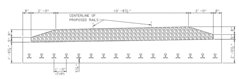
I'm looking at a rail slab bridge (concrete slab with steel rails near the bottom of slab), and I'm determining how to consider the contribution of the steel rails near the bottom of slab. I do not have details of any mechanical anchorage of the rails in the slab, so I would need to consider only the bond strength between steel rails and concrete. AASHTO MBE says that encased I sections can be considered composite at Service LS. I'm considering a check with an allowable bond stress to ensure that the capacity of the steel rails would be developed at the point where needed.

Does anyone have experience with this, or have any comments on this method?

Thanks,
 
Replies continue below

Recommended for you

structeng24 - Can you post a crossection (sketch is fine) showing "steel rails near the bottom of slab"?
Are the rails partially embedded in the structural concrete, or are they installed in "pockets", so that top of rail in more or less level with top of slab?

Often rail installation/maintenance is completely independent of bridge construction.

I would never consider the rail to simultaneously be stressed as part of a bridge's structural support system and carrying full load from a moving train. Rails typically flex visibly and move around quite a bit as a heavy train passes over them.

[idea]
 
I too would like to see a photo of the cross section as the rails being near the bottom of the slab sounds strange. Relying purely on concrete adhesion to the steel to justify composite action when no mechanical anchorage is present raises many questions. However, this sounds like something I would be faced with when load rating an old bridge.

AASHTO typically considers concrete encased structural steel shape members for columns or beam-columns. A purely flexural beam/slab is (IMO) not the intention of AASHTO. They do have some commentary under section C6.12.2.3.1 that seems to sort of address the topic but rather briefly:

Untitled_pzgntb.png
 
Thanks for the responses. The cross-section looks as shown below. The section of AASHTO MBE that I'm referring to is 6A.6.9.4, which deals with concrete encased steel I-sections in bending and I think this is similar to that.

cross-section_m0pzlh.jpg
 
structeng24 - I have not come across that design. Because of their size and location, appears the embedded rails will perform more like rebar than embedded I sections. But, you have to start somewhere... suggest making the calcs you have proposed to see what you get. Based on the results, you probably can make a better informed decision on what to do next.

Edit: Just noticed that the slab is not a constant thickness. What's that about? Superelevated on a curve?

[idea]
 
Well MBE 6A.6.9.4 certainly does address it. Good find.

First thing, have you guys performed an inspection of the soffit of the bridge? Is it in sound shape? If so, that may help to address your service level checks.

In regards to your strength level checks, have you read through the NCHRP report - Number 234? Link
 
We have performed an inspection, the underside is in good condition and sounds solid. There aren't any transverse hairline cracks present either.

I've read through NCHRP 234, the method seems more geared toward a slab on top of girder without mechanical connectors. I will look into this a little more though. It does mention a reasonable bond strength of 100psi, and suggests it can be much more for fully encased steel sections.
 
I feel your pain. I load rate a lot of strange bridges where it takes a lot of Engineering Judgement to come up with a rating factor. All of which incurs a certain level of liability on your part.

Just speaking out loud here trying to work through the problem. If hypothetically, at the ultimate strength level, the bond between the rails and the concrete did experience slip and the rails became "unbonded" from the surrounding concrete, couldn't your strength level check become an altered version of an unbonded PT strength level check for flexure? Because, then at that point you essentially have unbonded PT without the prestress component. The trick is coming up with your effective stress in the rail reinforcing "fps" to utilize in equation AASHTO 5.6.3.1.2-4. Since your effective stress in the rail could potentially be below its yield stress (different than how we would analyze typical bonded reinforcing) then your compression block and thus nominal moment capacity will be reduced.
 
...appears the embedded rails will perform more like rebar than embedded I sections

Except it wouldn't be reasonable to consider it as deformed rebar. Smooth bar or wire would be the closer analogy. In reality, the cross-sectional area to surface area ratio puts it somewhere between an "I" section and smooth bar.

Assuming this is a simple span, if you can figure out how to calculate the development length for a smooth, round bar of the equivalent cross-sectional area of a rail section, you could then reduce the capacity by partial development of the 'reinforcing' at various points along the span.

Rod Smith, P.E., The artist formerly known as HotRod10
 
Since there is no crack observed, maybe it is suffice to perform an elastic analysis on the composite section using ASD method. You may want to ensure the concrete cracking stress has not exceeded.
 
BridgeSmith said:
Except it wouldn't be reasonable to consider it as deformed rebar

I like to approach these problems from an upper-bound / lower-bound limit state approach. If the concrete was sufficiently bonded to the concrete, then the section could be analyzed as a regular reinforced concrete section which we could consider as our upper-bound threshold. Alternatively, if the rails were debonded from the concrete completely, then it would behave differently, is more difficult to analyze, and would have a lower capacity.... our lower bound-threshold.

In reality, it's somewhere in between. However, if the OP can rationalize that the lower-bound capacity is greater than the demand, then it makes his job a lot easier.

The basic development length of a #8 bar is 83 inches in 3000 psi concrete.

Force to yield a #8 bar = 47.4 kips

47.4 kips / pi * D * 83in = 182 psi. Now that's artificial since much of that bond is coming from mechanical bond and not just chemical bond.

Either way, compare that to AASHTO 5.7.4.4 and they allow you 25 psi bond for concrete cast on rolled structural steel. I think that value is too conservative. OP mentioned that NCHRP report talks about 100 psi bond.
 
Now that's artificial since much of that bond is coming from mechanical bond and not just chemical bond.

That's why I suggested using the development length for smooth bar, if such a calculation could be documented.

Either way, compare that to AASHTO 5.7.4.4 and they allow you 25 psi bond for concrete cast on rolled structural steel. I think that value is too conservative. OP mentioned that NCHRP report talks about 100 psi bond.

If 25 psi is the given value for concrete against a rolled shape (not encased), 100 psi seems like a reasonable value for steel encased in concrete. My very rough eyeball approximation of the rail gives me a 16" perimeter and 8 sq. in. area. Using those numbers and 50ksi yield (which is also just a guess), you'd need about 21' bonded length for full development.

How critical that is depends on the span length of the bridge.


Rod Smith, P.E., The artist formerly known as HotRod10
 
Status
Not open for further replies.
Back
Top