Continue to Site

Eng-Tips is the largest engineering community on the Internet

Intelligent Work Forums for Engineering Professionals

  • Congratulations KootK on being selected by the Eng-Tips community for having the most helpful posts in the forums last week. Way to Go!

steel trusses (angle sections) - gusset plate connection optimized with skew angle cut? 1

Status
Not open for further replies.

lolobau

Civil/Environmental
Dec 10, 2012
115
Hi

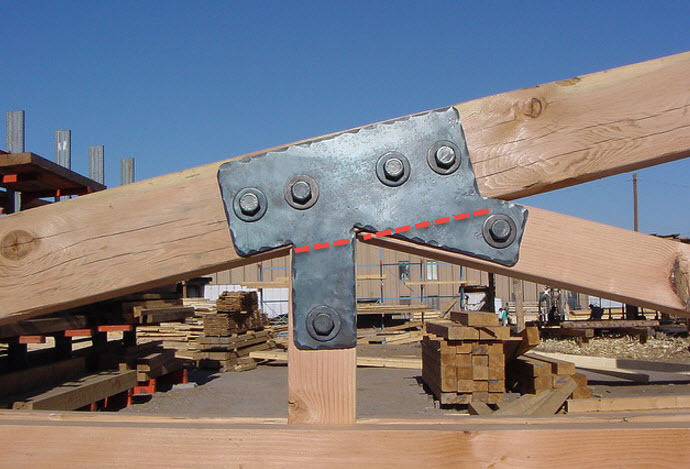
I was wondering why do we always cut the angle sections by truss connections straight?
When we would cut it parallel to the main bottom and top members then we could reduce the gusset plate size by a significant amount.
This would also lead to shorter "gaps" between the members fixing points which should be also better for the load transfer, or?
Am I overseeing something?

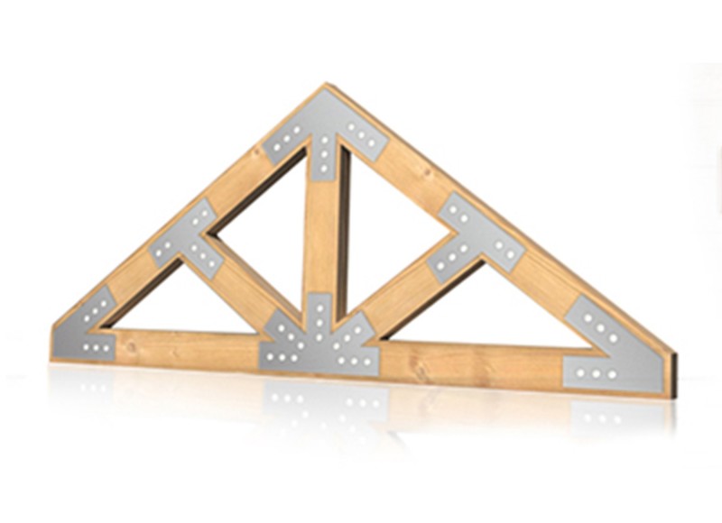
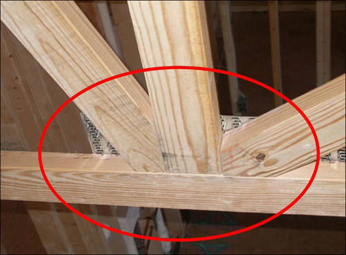
By wooden trusses this is usually done this way, so why not by steel?

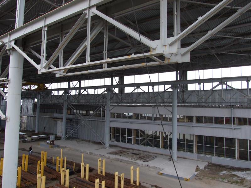
See attached images
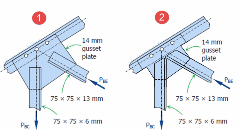

gusset_plate_-_two_options_skx7hk.gif


TRUSS_PLATE_1_1_oskstn.jpg


2017-08-23_9-57-32_xkbcsx.jpg


figure8_lepftq.gif


dscf1256_1_dwnxvu.jpg
 
Replies continue below

Recommended for you


Well...one issue could be....it is easier to cut the diagonal member perpendicular
probably much cheaper in production


best regards
Klaus
 
@ Klaus: this could be a reason but does it really make a big difference if you cut straight or skew? You need to cut anyway and you would save on the gusset plate size.
 
it does make a big difference
once in the design office...somebody need to draw all the different angels
angle on one side may be different to the other side
then it is easy to make errors, because how do you measure now the length of the diagonal ??

Same thing in the workshop.... need to change the cutting machine for each member
and also easy to make errors

so all these things makes it expensive ..


best regards
Klaus
 
@Klaus: hhmmm....ok you might have a point. So this is purely a practical reason for the cuts to be straight? No structural reason for it? Would you detail each gusset plate? This would be an overkill,or?

Reagrds

lolobau
 
I worked for a steel joist manufacturer, cost is definitely the issue.

In a single joist there could be a ton of different angles based on different member sizings. The design cost, and setting a machine up to cut each one differently would be far more than a little extra steel on the gusset plate. Also considering that you may find that plates come in standard sizes as well, and if your design calls for a minimum of 4.5" plate, 6" might be what's in the shop. They are going to leave that extra steel on because it's cheaper than cutting it to 4.5" and that 1.5" would just become scrap needing to be disposed of.

Keep in mind, for engineers optimization always has to come back to cost, not material. In some industries, like Aerospace and Automotive those are tied together in the overall lifetime of the vehicles, fuel saving will be cheaper in a lighter vehicle, in fields like Civil Engineering, usually minimizing construction labor is more important than a little material, not always, but usually.
 
@gravityandinertia: Thank you so much, you effeminately opened up my eyes and convinced me. Ok agree now ;-)
 
ok, so the one question is sorted but now I get another question.

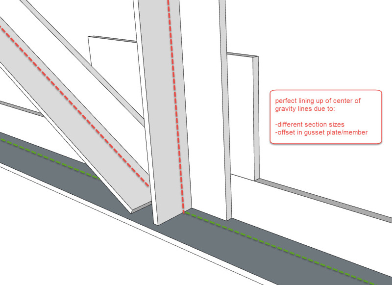
Why am I seeing always the gusset plates outside of the member? Why don't we weld it inside? The center of gravity lines would then even line up much better

see attached image is version B and C not the best solution? and most ecconomic?

gusset_plates_bgezyt.jpg
 
C is more expensive because you need to have a CJP weld between the gusset plate and the leg of the angle. Personally, prefer B over A.
 
Typically the point of a gusset is to be able to increase your weld length because your loads are to in your web members for the sizing of your top or bottom chords to get enough weld to safely transfer the load. With that said, your image B would be preferable, because for the proportions shown in A, you haven't really increased the amount of welding length and more than you would have just welding it to directly to the bottom chord. In image B, you have increased the available weld length, there is much more overlap between the web member and the gusset there.
 
@gravityandinertia: you very right but then why not version c? there you also have the increased welding area but you recuse the gusset plate.

Do designers actually look into best lining up of center of gravity lines?
see image below

2017-08-29_16-54-46_vhsryt.jpg
 
when you detail a truss, would you give all the dimensions of all the vertical and diagonal members as well?
dimensions of gusset plates? or is it going to much into detail?

 
AS slickdeals indicated, detail C requires a CJP weld between the gusset and the bottom chord, this is a costly weld. Much more costly than the extra plate due to the prep work involved for a CJP weld. Plate is cheap.
 
@Jayrod: convinced ;-) thank you guys for opening up some new perspectives for me. Ok so C is out but then B shoudl be the optimum setting out when your inner sections are smaller to line up the center of gravity lines, or?

 
@Joyrod: Just out of curiosity, why not then VERSION "A"?
 
@lolobau

There are a couple more things about why B, not C as Jayrod indicated cost of the weld for one. On top of that, you can get more weld length in B on the gusset and along multiple faces which is good for redundancy, though that's sort of a tertiary benefit. The last thing would be that in B, the leg of the channel and the gusset stiffen each other more than occurs in detail C, which overall makes the joint stiffer.

Lastly, yes there is care taken in lining up centerlines, ideally all coming together at a point on the joist, in practice due to space at the connection it rarely happens.
 
B allows more weld length for the web members without increasing the plate size. And it looks cleaner. A is acceptable, but B is likely the way even the fabricator would want to do it.

Depending on the member sizes I doubt that C would really benefit you significantly in lining up the centrelines of each member. The slight eccentricity introduced in A and B likely shouldn't change the design significantly.
 
Wood trusses usually depend on transferring compression loads from one member to the next through bearing. That is, one member bears on the other as depicted in the sketch of the wood truss.

Steel trusses on the other hand transfer the loads, both compression and tension, through the connection plates. In extreme cases, if the web members are too short and the connection plates too thin, localized buckling can occur when subjected to compression. It is the old kl/r trick.


Best regards - Al
 
Status
Not open for further replies.

Part and Inventory Search

Sponsor