Continue to Site

Eng-Tips is the largest engineering community on the Internet

Intelligent Work Forums for Engineering Professionals

  • Congratulations Danlap on being selected by the Eng-Tips community for having the most helpful posts in the forums last week. Way to Go!

Stiffeners at Skewed Column Transfer

Status
Not open for further replies.

efFeb

Structural
Dec 25, 2019
67
Good Morning,
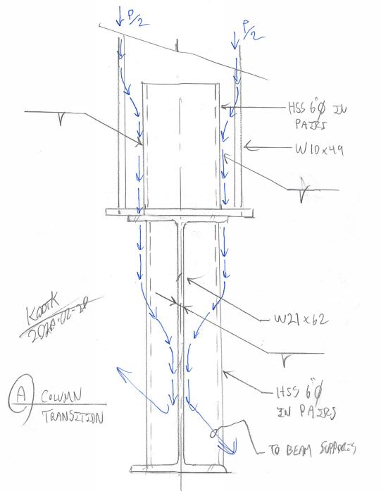
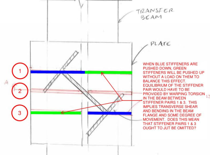
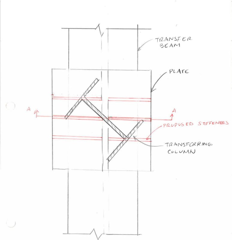
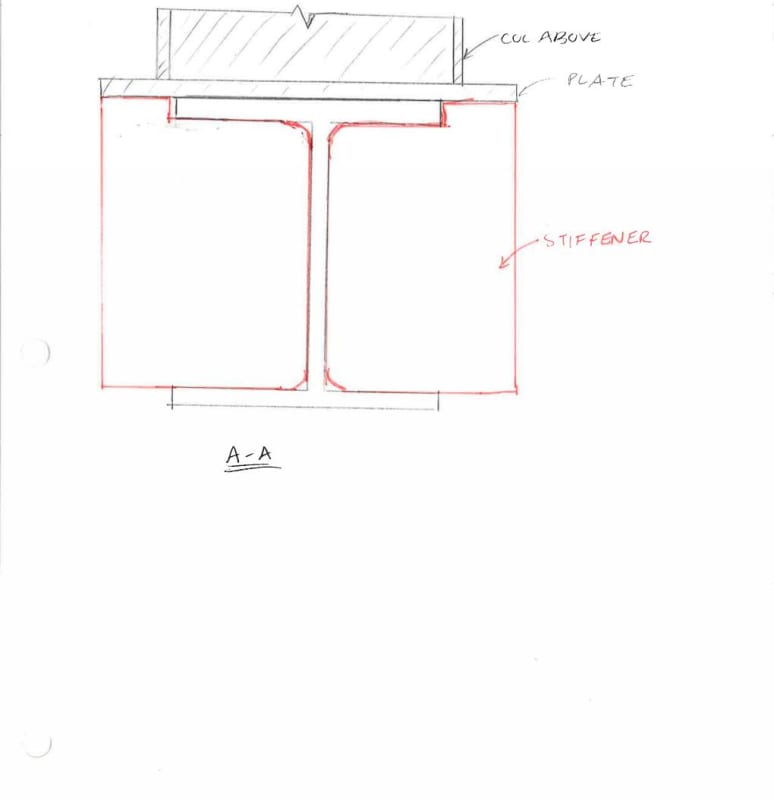
I'm designing a steel transfer structure, where a number of the transferring columns are skewed relative to the supporting transfer beam. Thinking about this, I would like to include a stiff plate below the transferring column, and then include stiffeners extending the full width of the plate. I've attached a sketch of what I am thinking to do here. If anyone have any thoughts about this approach or any input / resources that might relate to this condition, it would be greatly appreciated.
Thanks so much!
column_transfer_Page_001_opv8n5.jpg

column_transfer_Page_002_qzqwq1.jpg
 
Replies continue below

Recommended for you

I see your dilemma and I appreciate what you're trying to accomplish. You're definitely on the right track.

I feel that a worthwhile goal here is to get as much steel column area over top of stiffeners as possible. It doesn't have to be the entire column area, or even close to that, but As x Fy should work over that area without any local buckling issues.

See the the sketch below for one idea for a stiffener arrangement. Not super fun to fabricate but it mechanically sound. If you could run some short plates across the flanges of the column near the base to make that a box section too, all the better. Note that some folks consider a closed off space to be a fireproofing issue. I'm not convinced of that myself but it's something to consider.

c01_qcyqkl.jpg
 
Or maybe stiffeners on top...

What is your axial load as a percentage of the column [phi x As x Fy] here? That would be helpful as an index of the scale of your problem.

c02_uuzboa.jpg
 
I'm out of control... detailing threads are like KootK crystal meth.

c03_wgwsrk.jpg
 
Another option here, similar to what KootK first proposed, is to use half (or maybe 1/3) of a round HSS section on each side of the web, instead of the pairs of plates. We have used those for the bearing stiffeners on a few bridge superstructures.

Rod Smith, P.E., The artist formerly known as HotRod10
 
I second the top web stiffeners in the column aligned with the web of the transfer girder, but another option would be to cut a WT from the same shape as the column section. Make the WT fitted to the flanges of the transfer girder, and fillet weld all around the accessible areas.
 
Oh... my... gawd! This isn't quite rod's solution but, thanks to his inspiration, I'm pretty sure that this is the sexiest of all possible solutions. Mechanically perfect and pretty easy to fab. We should all get the afternoon off now.

c04_mamgmn.jpg
 
EfFeb:
That is a crazy mess. The idea is to provide proper bearing for the end of the col., on top of the transfer beam, and to get the col. loads (and moments) down into the web of the transfer beam. If I could I would eliminate the pl. btwn. the col. and the top of the beam. But, we need to know the details at the bot. of the existing col. to make this determination. Also, what are the sizes and dimensions of the col. and the transfer bean, and the angle and location of their mating, and the actual loads? I would get a length of that col. section or heavier in the same group class, approx. same flg. width, and cut it to length to fit btwn. the inside of the flgs. on the transfer beam. Then, rip the col. piece web to fit and match the transfer beam web angle and match the col. from above. You may not even need this col. piece to have a perfect (bearing) fit at the transfer beam bot flg. Clip a few web and flg. tips on the col. piece, do some weld detail prep. and weld to the web and top flg. of the transfer beam. The welds to the transfer beam web would be one sided PJP groove welds and those to the flg. would one or two sided fillets. I’d want to do some layout to see how this all fits up.

Is the col. load 1000lbs. or 1000k, and what about the sizes of the beams and cols? Can you imagine that some of these minor details might influence the analysis and design of a detail like this? Sketch proportions are also important if you want meaningful discussion on your problem. They don’t have to be perfectly scaled mech. drawings, but they should convey the correct first impression. It’s the old…, 12” brick corbel or 100’ flag pole, they’re both cantilevers, except…
 
Thank-you all so much for your ideas! I really appreciate it. I'm going to have to give the HSS solution some thought to figure out how the force would actually get to the web below along this curve.
dhengr, to answer your questions, columns are all skewed 45deg to the transfer beams. Typical columns are W10x49 and a typical transfer beam is W21x62. Factored loads are around 350kip.
Thanks again, I'm going to give this some more thought with all of your input.
 
This would be the load path for my last scheme. I drew it at 90 instead of 45 on account of this not being art class. W10x49 is nothing; hardly bigger than my massive forearms.

c01_hy6xap.jpg
 
For those size members, I think the proposed bearing plate and stiffeners in the original sketch should work just fine. KISS.
 
It would seem to me that if you employ the 6" HSS around the column, you could dispense with the bearing plate, or alternately, include the bearing plate and not the 6" HSS.

For bridge girder bearing stiffeners we do pretty much the same thing, only upside down. We don't really concern ourselves with the internal shear flow through the stiffener. We just check the slenderness (moment of inertia) for buckling. With the half-circle welded to the web on both edges, the resistance to buckling is extremely high; much higher than a plate. At less than 21" in length, if you checked the HSS section for buckling as a plate (which would be massively conservative), the required wall thickness would still be fairly small.

Rod Smith, P.E., The artist formerly known as HotRod10
 
Fun thread. The HSS solution is pretty sweet. Some general factors to consider:

1. On the original sketch with the three stiffeners, make sure that you have weld access to get in the welds on the center stiffener and the inside of the outer stiffeners. A good way to check is to project a line at 45degree out to the edge of the stiffener. Anything that is within that bound will make it a difficult job to weld (thus more $$$).

2. The HSS corners will need to be clipped because of the k distance on the beam. This was shown on the original sketch of the stiffeners, so I think it's still observed as a necessary detail. It just means a little more fab coordination, but is not the end of the world.

I like the stiffener idea (KISS) and think you can make it work. I would keep the base plate on the column rather.
 
skeletron said:
On the original sketch with the three stiffeners, make sure that you have weld access to get in the welds on the center stiffener and the inside of the outer stiffeners. A good way to check is to project a line at 45degree out to the edge of the stiffener. Anything that is within that bound will make it a difficult job to weld (thus more $$$).

Is there anything stopping us from welding only one side of a stiffener? Even we welded the top of the stiffener on two sides but the side of the stiffener on only one, I'd think that the stiffeners could be installed sequentially without weld access issues.
 
Something about the originally proposed stiffener arrangement has caught my eye. Forget, for now, that the loads here are likely so small that anything will work. Imagine big, scary loads.

c01_hatw2x.jpg
 
Hmm...Only if the loads were high enough that they cause local yielding of the column web when the loads are focused through the point where it aligns with the web of the beam. Until that happens, I think the concentric load transfer is dominant. Once the torsional stiffness of the beam is greater than the stiffness of the web due to plastic flow at the point of contact, the beam will be engaged in torsion (albeit over a pretty short length).

I would remove them, but not necesarrily for the torsion reason. With a W10 column, the spacing between those plates can't be more than 2". I've never met a welder with hands that small.
 
phamENG said:
Hmm...Only if the loads were high enough that they cause local yielding of the column web when the loads are focused through the point where it aligns with the web of the beam.

Right, but if you never get to that point, then there's really no sense in having any of the stiffeners. I believe that the idea is to create multiple points of contact that are each stiff enough that one can assume that they're sharing the load. The question with this is whether or not that's true when the load on a stiffener pair is unbalanced and beam torsional resistance is forced to come into play, albeit over a short distance.
 
I agree with you, but I don't think it's going to be significant at first. The load is going to be shared between each part of the connection in proportion to various stiffnesses of the elements, right? Well, which is stiffer - the concentric axial force transfer from column flange to beam flange through the area where they overlap, or the twisting of the beam's cross section? Seems to me the axial load path is stiffer. So, yes, the beam will be resisting some load through torsion, I don't think it'll dominate as long as the axial path remains viable. After all, most of the efforts of the methods employed above are centered around keeping the load centered, right?

I just re-read your post, and I think I'm arguing past you, and not addressing your question. Sorry about that. I'll give it another stab.
Edit to my edit - you edited your post. My original post was addressing your original post. I'll let it stand.
 
I think from the torsional side, since this is a transfer beam there is structure around... just kick it over to the deck of somewhere adjacent to eliminate that aspect. Part of me says that is necessary with all these solutions as a W10 has a decent base moment to resist... say we want to resist the axial capacity at 3" off axis ... or 10% of moment capacity, it will put an odd force into the transfer beam. I guess i usually try to brace transfer beams by someway in the weak direction anyways always.

So, if you put a pipe around the transfer beam, then you can easily put a shear tab on said pipe and use that as a torsional brace in any direction.

 
Status
Not open for further replies.

Part and Inventory Search

Sponsor