Continue to Site

Eng-Tips is the largest engineering community on the Internet

Intelligent Work Forums for Engineering Professionals

  • Congratulations Danlap on being selected by the Eng-Tips community for having the most helpful posts in the forums last week. Way to Go!

Stiffeners at Skewed Column Transfer

Status
Not open for further replies.

efFeb

Structural
Dec 25, 2019
67
Good Morning,
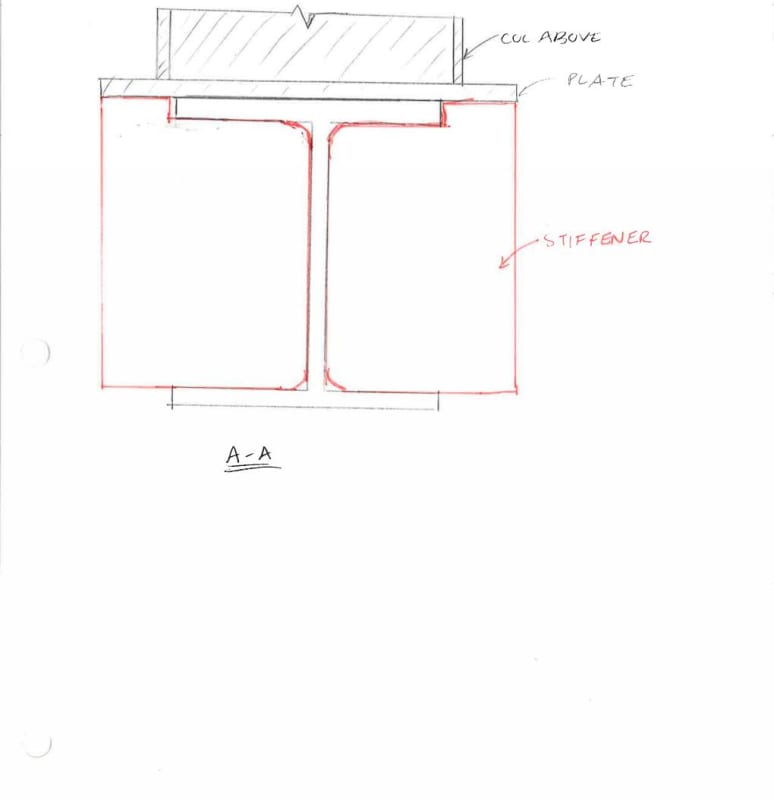
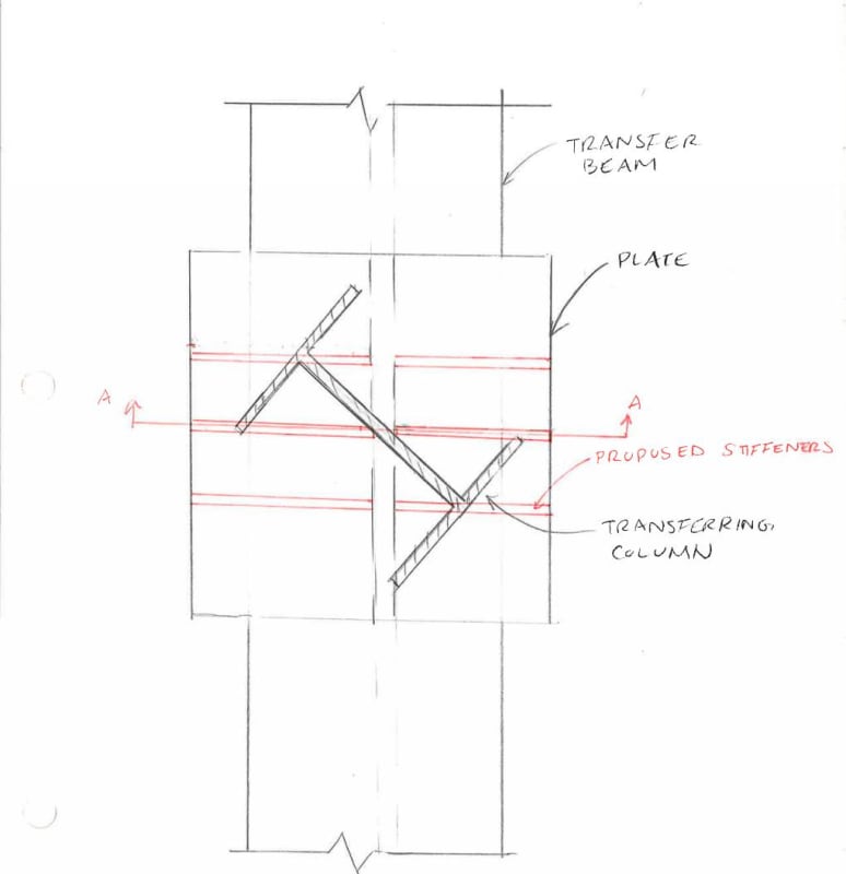
I'm designing a steel transfer structure, where a number of the transferring columns are skewed relative to the supporting transfer beam. Thinking about this, I would like to include a stiff plate below the transferring column, and then include stiffeners extending the full width of the plate. I've attached a sketch of what I am thinking to do here. If anyone have any thoughts about this approach or any input / resources that might relate to this condition, it would be greatly appreciated.
Thanks so much!
column_transfer_Page_001_opv8n5.jpg

column_transfer_Page_002_qzqwq1.jpg
 
Replies continue below

Recommended for you

I think the OP was to create a box to engage the bottom flange in resisting/distributing the torsional effect, also to have the benefit of stiffen the flanges to lessen distortion of the beam web.
 
To address your edited post, KootK, you have a good point. I usually employ stiffeners to prevent web instability failures in the beam (buckling, crippling, etc.). When it's convenient, I make them align with flanges or webs of connecting members. It makes for a more logical load path that doesn't require as much mental processing time and provides a generally more robust connection. In this case, I would probably go for a central web stiffener and a thick plate on the column. That would probably be sufficient for all but the scariest of scary loads, and would prevent the RFI's ("who the #$*& puts a pipe in a column?" - Joe Schmuckately, GC) and any concerns (whether correct or misguided) about fireproofing inside the not quite sealed pipe segment, if fireproofing is being applied.
 
EfFeb:
I’d use a 16-18” length of a W10x45. Its flg. width and thk. and web thk. match nicely, as does the member depth. If you snap a line from the inner tips of the two diag. opposite flg. corners/tips, and cut the web on that diag. line, the two halves will fit perfectly within the transfer beam and up under the existing col. Again, some weld prep. and clipped corners on the web and one flg. tip on the top should do it. And, there are half as many pieces and much less welding involved. .25” or .31” fillets, or equivalent welds to the beam web should do the trick, along with some fillets to the underside of the beam top flg. In plan view, these two new stiffener pieces are literally hidden by the existing col. above. What does the existing col. base pl. look like, and bolt holes too?
 
phamENG said:
I agree with you, but I don't think it's going to be significant at first. The load is going to be shared between each part of the connection in proportion to various stiffnesses of the elements, right? Well, which is stiffer - the concentric axial force transfer from column flange to beam flange through the area where they overlap, or the twisting of the beam's cross section? Seems to me the axial load path is stiffer. So, yes, the beam will be resisting some load through torsion, I don't think it'll dominate as long as the axial path remains viable.

Maybe you missed how I defined the problem originally.

KootK said:
Forget, for now, that the loads here are likely so small that anything will work. Imagine big, scary loads.

Stiffness is an irrelevant argument for this except, perhaps, to say that the lack of stiffness at the stiffeners in questions neuters them. Imagine big, scary loads for which each of the stiffeners needs to be doing its intended job for real. In a way, you're kind of making my argument for me here in that, if the questionable stiffeners are insufficiently stiff, they may not prevent column web crippling.

phamENG said:
After all, most of the efforts of the methods employed above are centered around keeping the load centered, right?

So what? I'm only commenting on this one method, not the rest of them.
 
EE said:
Just kick it over to the deck of somewhere adjacent to eliminate that aspect.

I question this. To brace the effect that I'm questioning, you'd be seeking to brace for a load generated by 1/7 th of the column reaction. For a hypothetical, seriously loaded column, I feel that will be more than one ought to be trying rectify with a light duty deck kicker.
 
phamENG said:
In this case, I would probably go for a central web stiffener and a thick plate on the column.

So would I, for the real case presented here (as opposed to my hypothetical case). It gives you five, stiff, pickup points at which to deliver concentrated reactions into the column plate elements.
 
I agree that a scary load would not work with a L4 kicker to the concrete deck! sorry i wasn't trying to get into that scary load debate! :)

I was actually meaning the load that we likely have, which isn't scary big... so 1/7 over a force couple that is the depth of the transfer beam isn't too horrible. And I guess i am comparing this to the case of no-kicker vs w/ kicker. The 45-angle axial i think can be handled with web stiffer elements or the pretty pipe idea, but the base moment of the column needs a little more attention, hence a brace?
 
EE said:
...but the base moment needs a little more attention, hence a brace?

Where are you getting this base moment from? I don't see it. But, yeah, this would certainly a rational place for a feel good, nominal LTB brace. Count me in for that.
 
KootK-

Focusing on this method: once we get to that point, there will always be some amount of load transferred to the beam inducing torsion on either side of the center of the connection. So the warping resistance between those points will always be a limiting factor. In that case, the stiffeners act to reinforce the beam and inhibit local failures (primarily bending in the flange).

As for keeping the load centered, I was unsuccessfully comparing the virtues of the methods. You either have to depend on the torsional resistance within the space of the connection (between flanges/stiffeners), or you reinforce the point where the webs cross and eliminate that reliance on torsional resistance.

I think we are agreeing with each other on most points?

 
phamENG said:
...there will always be some amount of load transferred to the beam inducing torsion on either side of the center of the connection.

I disagree. And that's precisely why I feel that some arrangements may be better than others.

c01_my5e3o.jpg
 
I think we're talking past each other again. The line you quoted from me there was referring to having the outer plates in place.

Your image only works if your column flange is equal to the column depth and the column is skewed 45 degrees. Any other combination is going to result in one of your points being off of either the web or the stiffener. Granted, that is precisely the condition we have here - but since we're adjusting the loads we might as well adjust the section to cover a broad scope.

That's where having the thick plate comes in - thick plate plus stiffener will negate the torsional effects by effectively centering the load. As long as the plate is thicker than the beam flange, a single stiffener under would likely be enough to prevent any noticeable torsion from developing within the connection regardless of the angle and flange widths.

So, yes, some arrangements are better than others - namely, those that eliminate the reliance on torsion within the connection.
 
phamENG said:
I think we're talking past each other again. The line you quoted from me there was referring to having the outer plates in place.

Any chance you'd like to post a sketch of the situation that you want to discuss? I'm really struggling to follow along.

phamENG said:
Your image only works if your column flange is equal to the column depth and the column is skewed 45 degrees.

But, as you mentioned, that is exactly the case here. Objection not sustained.

phamENG said:
Granted, that is precisely the condition we have here - but since we're adjusting the loads we might as well adjust the section to cover a broad scope.

Hard pass. It's been hard enough trying to track this conversation without throwing the gates open even wider. Sticking to a limited discussion of OP's original stiffener arrangement would be my preference for discussing the particular torsional issue that I tabled. See the clip below.

phamENG said:
That's where having the thick plate comes in - thick plate plus stiffener will negate the torsional effects by effectively centering the load.

I disagree and contend that, the minute you have a girder-web-balanced stiffener that crosses the column cross section, that's going to start drawing a disproportionate amount of the load. Unless we're willing to start talking 4" base plates, that's going to remain true. I see the base plate's function, at any reasonable thickness, as that of localized base plates in micro. Wherever plates cross and form hard spots, the plate widens the contact point out some.

phamENG said:
...a single stiffener under would likely be enough to prevent any noticeable torsion from developing within the connection regardless of the angle and flange widths.

Let's leave the single stiffener arrangement out of this part of the discussion as it does not exhibit the torsional issue that I've proposed for consideration.

I'm not sure if this is what's confusing people but I'll through it on the table anyhow. No arrangement, with or without a thick base plate, will produce a net torsion on the girder taken as a whole. The torsion is a localized effect that is introduced and then countered over a short length of the girder so long as there is symmetry in play.

c01_ktnf36.jpg
 
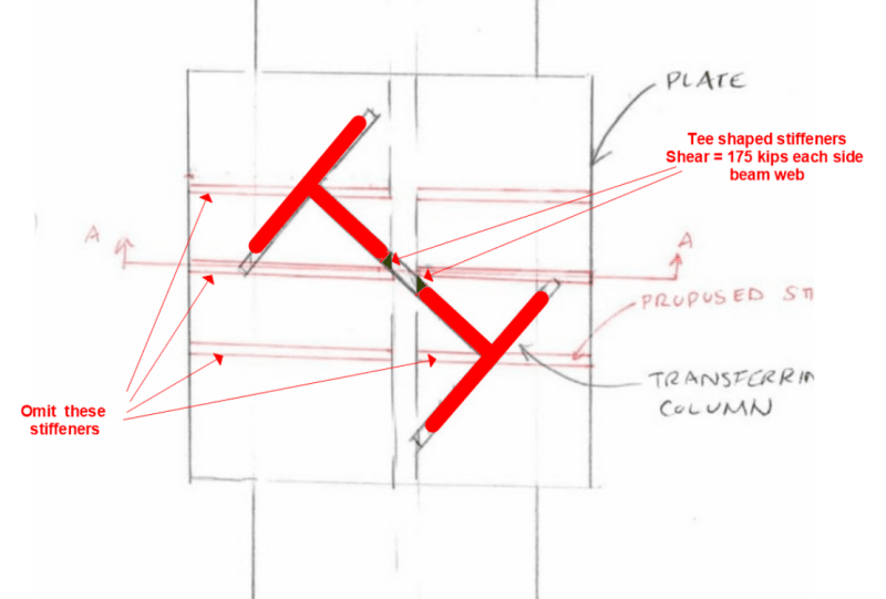
Two tee shaped stiffeners aligned with the skewed column and fitted between the flanges of the W21x62 seem to offer the simplest and best solution. The stiffener flange and web should be bevelled top and bottom to permit welding from one side only. Backing plate may be used. Web must be thick enough to transfer 350/2 = 175 kips factored shear each side of the beam web. Flange must be large enough to provide enough bearing area.

Column base plate doesn't do much other than to connect column to beam flange. Half inch thick with 4 bolts sounds reasonable.

There is no torsion in the beam unless there is moment in the column but even then, beam rotation is controlled by the stiffness of the skewed column.

ColumnTotransferBeam_eyhhxh.png


BA
 
Status
Not open for further replies.

Part and Inventory Search

Sponsor