Continue to Site

Eng-Tips is the largest engineering community on the Internet

Intelligent Work Forums for Engineering Professionals

  • Congratulations waross on being selected by the Eng-Tips community for having the most helpful posts in the forums last week. Way to Go!

Stiffening HSS Column 1

Status
Not open for further replies.

UofIgrad17

Structural
Feb 20, 2019
13
This is my first thread on here so I wanted to say hello to everyone and how much I appreciate the community.

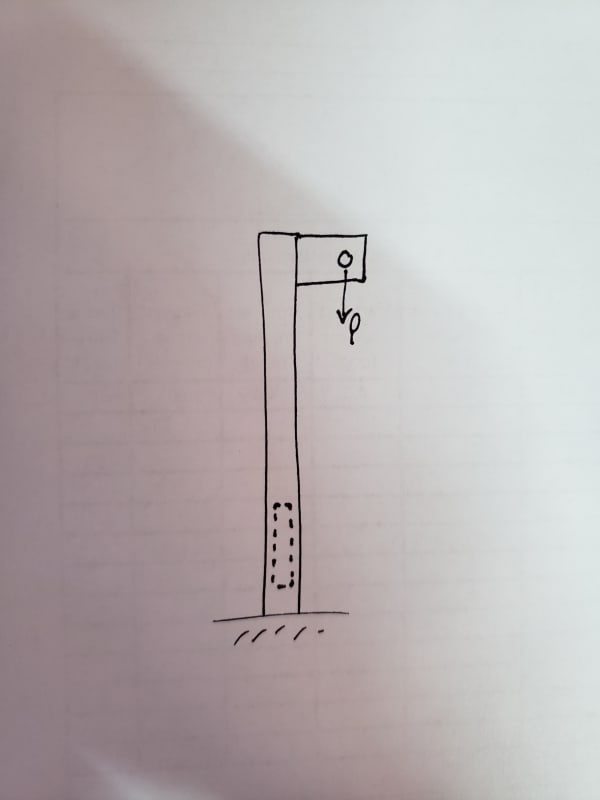
I'm currently a structural engineering intern so I'm learning where real life and academia tend to clash. I'm working on a device that is going to be used to prevent falls from ladders. It is a 2x2x1/8" HSS tube with a plate welded outward from the top to give a point to attach to. The column has to withstand an axial force downward of 5k and, due to the attachment being away from the tube, it resists a moment as well. Preliminary testing showed flexural yielding in the member about 6" from it's support at 4.5k. After rechecking numbers and calcs, I realized that the member fails due to combined flexure and axial forces. The client does not want to go up a size due to weight issues, so I've thought to add rectangular bars to the sides of the HSS tube to stiffen it. My question is if I can use the nominal flexural strength calculated in Section F11 of AISC and simply add it to the nominal flexural strength of the tube itself. Similarly, use the nominal compressive strength calculated in Section E3 and add that to the nominal compressive strength of the tube. Some additional questions would be if the bar would need to span the entire length of the tube or if I could manage only having it for the section (about 18" long) of the tube that yielded during testing. I planned on stitch welding it as well. Any help would be greatly appreciated, thank you!
 
Replies continue below

Recommended for you

A sketch would help, but if you're welding two pieces together you're creating a composite section so the flexural strength wouldn't just be a simple summation of the two pieces added together.
 
20190220_102944_a6tugb.jpg


I've attached a sketch. The dashed area is where I was thinking of welding the bar on. The thought of it having to be a composite section crossed my mind, but I wasn't sure exactly where to find the spec calculations for this as the composite section mostly refers to concrete and steel together.
 
As jtb said, a sketch would help. From how I'm visualizing it, it seems you may be able to solve your problem by extending the connection plate farther down the tube(?)

Edit: With the overstressed area there, my first stab at it won't help.

 
Please see the sketch above. Unfortunately, the connection plate cannot come down any further. There are two iterations to the design, one short and one long. The long one is giving the issues.
 
Composite design with 2 steel sections is fairly straightforward - just calculate the section properties for the single piece the shape of the combined sections. It's just like with a steel and concrete composite, except you don't have to transform anything.
 
It's hard to imagine how bumping up to an HSS 2 1/2 x 2 x 1/8 would add enough weight to matter, especially with 5 kips applied. Edit: An HSS 2 1/2 x 2 1/2 x 1/8 is less than a pound per foot heavier. If adding less than 20 lbs to something carrying 5000 lbs is too much weight, I'd say it's being designed too close to the edge - if the assumed 5 kips is actually 5.02 kips you're screwed? That's not not a design approach I'd be comfortable with.

Any chance of reducing the eccentricity a bit?
 
I had a "duh" moment where I realized that it's just treating it as a built-up member. I don't suppose there's a way to calculate the length that the bar needs to be however. Since the axial force and moment is essentially uniform throughout the tube I'd imagine the bar would have to span the full length.

I mentioned to the client to go up in weight, but he has to carry this device up the ladders to install it himself and is already having trouble with the current weight. However, adding a 1/8"-1/4" bar along the whole span wouldn't be too different I'd imagine so I'll try to bounce that idea off of him again.
 
I also played with reducing the eccentricity, but you'd have to essentially be at the face of the post to pass combined flexure and axial loads, which isn't an option. I like the idea of using a rectangular 2 1/2 x 2 x 1/8 as the difference is less than half a pound per foot, but I can't find a supplier with that particular size.
 
If its a matter of weight and not the size of the cross section then it may be worth switching to aluminum. 169 lb/cubic foot vs 490 lb/cubic foot for aluminum vs steel respectively
 
Size is of some importance simply because he'll be carrying it up the ladder so it can't be too bulky (it's already 8'3" long). From a cost standpoint, I also doubt he'd want to go the aluminum route. I calculated that a 3 x 1 1/2 x 1/8 tube will handle the forces and is only adding 0.43 lbs/ft. Adding just a 1" x 1/8" bar on one side will add 0.425 lbs/ft so I think that the obvious option is going with a rectangular tube. I'm glad that HotRod10 pointed out that option, because I just disregarded using a rectangular tube thinking the appropriate strength would be too heavy. Thanks for all the advice!
 
Busy day today so I'll make this brief:

> Double check your loads - 5,000 lbs is a very high arrest load to design for (typically non-engineered anchor points need to be good for 5000lbs)...check your governing code, you can probably get away with twice the max arrest force (likely 2x900 lbs = 1800 lbs).

> Your device assumes that the worker will fall perfectly in-line with the post (single axis bending with axial) when in reality you're likely to have the load applied at some angle (bi-axial bending, torsion, axial).

> If you strengthen this with a plate, it should be extended all the way down to the base. What does the base connection look like? If this is exterior use and the plate isn't too large I'd go for continuous weld vs stitch weld just so it seals up nicely.
 
So this 8'-3" long device that is supposed to prevent someone from falling off a ladder must first be carried up the ladder and attached to something. Seems backwards.

I'd say the best chance of falling off the ladder is while trying to carry this thing up a ladder.

Sidenote....what is the design or load criteria that it needs to be designed for? Some fall protection requires the load to be applied in ANY direction. Does that change your design?
 
Thanks CANPRO! I'm not sure exactly why they require 5000 pounds for a simple ladder safety device that probably will never see more than 500 pounds on it. The funny thing to me is that the device withstood the dynamic drop test, but failed the static test. Since the dynamic drop test passed, so I'm not worried about the bi-axial bending or torsion. The base of the connection is bolted to a ladder rung and a few feet up there is another point which essentially behaves like a fixed support, then the remainder of the tube is free standing as shown in the sketch above.
 
MotorCity, please see my response to CANPRO for testing criteria. I definitely see the flaw in logic of installing this device, but that is how the client that's selling them sees it best to install them I guess. I'm sure he has some sort of harness himself with carabiners or something similar to protect himself, at least I'd hope. [lol]
 
Ok, the weight issue makes more sense now. If the moment is only in the one direction, you could look at a rectangular HSS, such as a 2 1/2 x 1 1/2 x 1/8, or possibly a channel section (C3x3.5 is 0.45 lb/ft heavier but Sx is nearly double that of the HSS 2x2x.125)
 
Can you use a higher-grade material?
Can you use rectangular instead of square?
If you add the bar, you can put it on one side, not both sides, put it in line with the load instead of at right angles, etc.
Take a good look at the load requirements, and see if it has to (just) support that load, support that load with no damage, support that load without exceeding allowable stresses, etc.
Perhaps use an oversize base section with the upper section telescoped into it and welded- similar to how they do flagpoles. (Note, a close fit of one tube in another may run into issues if the corner radii don't match up right.)
 
HotRod10, as far as I know, channels typically are only made of A36 steel correct? I'd be taking a hit on strength there. I think rectangular HSS is the best route to take. The smallest size that would work that I could find online was a 3 x 1 1/2 x 1/8. Thinking now to CANPRO's comment however, this member is skinnier in the weak axis direction and therefore may not behave in the drop test the same way that the 2x2x1/8 tube did. I believe the drop test is only a 282lb weight from 3 feet. I'm a little removed from dynamics but I believe this comes out to about 850 ft-lbs of energy. I'm not really sure how to convert this to a force apply this to weak axis bending however.
 
JStephen, I'm pretty sure the standard HSS material is A500 Gr. B and not really sure where to find higher grades anywhere else that are readily available without significant cost increase. I think I'm going to take the rectangular HSS approach, but trying to determine the best way to calculate for the drop test. The criteria is a 5000 pound static load test, and a 282lb drop test from 3 feet with no damage or yielding. I have the static load test calculated for, but not sure for dynamic load. I believe in order to match the 5000 pound impact force, the weight would need to travel about 2 inches of "slow-down" distance. I think that this is obtainable, but my worry comes from an off-center impact force as CANPRO pointed out that would cause biaxially bending. My initial thought is that the max angle is minimal (less than 10 deg.) and therefore can largely be neglected since the weak axis won't experience much of it.
 
How are you determining the maximum angle? I doubt this device is installed at the center of the ladder - so when the work is as close as he can get to the anchor point and falls, the angle may be more than 10 deg. If you haven't already done so, I suggest doing a thorough code review (in Canada there would be national standards to review and local OHSA regulations) before spending too much time guessing at things that are code requirements - where I practice I'm fairly certain there are ranges of use you need to consider, which would dictate the design angle.

Taking a step back on this - you mentioned the post is being anchored to the ladder rungs. Is this allowed? Sounds fishy to me. I hope you put a big ol' disclaimer on your final drawing that the ladder has to be reviewed on a site specific basis. Also, the connection the ladder rung sounds like it would block your hand from fully grasping the rung - good thing there is a fall arrest system installed!
 
Status
Not open for further replies.

Part and Inventory Search

Sponsor