Eng-Tips is the largest engineering community on the Internet

Intelligent Work Forums for Engineering Professionals

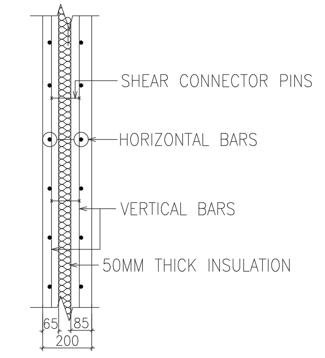
Stiffness modifier for insulation panel in ETABS 3

Status
Not open for further replies.

ak.t

Structural
Dec 18, 2019
73
0
0
AE

Dear All,

If I define the wall as insulation wall panel (max thermal transmittance, U-value of 0.57 W/m2K), what could be the value of stiffness modifier to be specified in ETABS to obtain an actual behavior??

Thank you,
 
Replies continue below

Recommended for you

Dear Dreber & Enhineyero,

Yes. It is a load bearing precast concrete walls that consist of two concrete layers joined by stainless steel connectors with an insulating layer between them. The insulation layer is continuous over the entire surface area.

insulation_panel_i4isph.png
 
I've never modeled a wall like that before, but I would consider conservatively modeling it as two separate concrete plates and neglect the insulation and the steel.

If this is structural, you may consider advocating for a different assembly. Insulated concrete panels have been around for awhile and seem a lot easier to use, at least from an engineering point of view.

=========================
David Reber
 
Does dreber answer your question? Otherwise you need to explain what is "stiffness modifier", and its application in the program.
 
Dear retired13, I think No. Ok, I will share a link for explanation.

Dear dreber, for Stiffness modifiers, kindly follow this Link and for Etabs input for the same Link

Thank you,
 
I think your question has been well answered in the linked paper,

Walls are generally not designed for out-of-plane bending to avoid excessive longitudinal reinforcement. In this case, use a small modifier say 0.1 for m11, m22 and m12 so numerical instabilities could be avoided. However, use m11, m22, m12 = 0.70 (or 0.35) when considering the out-of-plane bending in wall.

So the key is - does the panel suffer significant "out of plane bending", which usually does not. You should calculate Ig assuming a composite wall panel with void space in between, then apply the modifier accordingly (follow the suggestion above).
 
OP, follow the recommendation of retired13 and dreber, model them as two separate plates and apply modification factors as stated above, although I would be careful in using this detail. The wall will essentially be 65mm and 85mm thick, that's not a lot.
 
Aksahikas,

Set the stiffness modifier for m11, m22 and m12 to 0.1 for your case should be sufficient.

I guess now I know your confusion - why the modifier is to be set so low for an un-cracked wall panel. Simply put, unless there is a applied normal force causing large bending in the wall panel, it is undesirable to draw large forces from other members, that are connected to the same joint, to the panel. To prevent the undesirable action (draw excessive forces) to occur, the stiffness of the wall panel shall be reduced to represent a flexural weak member in the framing system.

Let's consider an example for effect of member stiffness in structural analysis. Say there are 3 members connected to a common joint, with stiffness of I, 2I, and 3I, respectively; now a 6'-k torsion applied to the joint, what is the share of torsional effect of each member at the joint? Keep in mind the share of an individual member is calculated as "stiffness of the member divide the sum of stiffness of members in the system". I hope this makes sense to you.
 
@AkshikaS:

What is the nature of the problem that you're trying to solve with your ETABS modelling? If the walls are not prestressed and you're seeking an appropriate wall stiffness estimate for a global, lateral load analysis of the building, the solution is simple: model the wall as you would a conventional, reinforced concrete, 150 mm wall.

If you're seeking to accurately model the out of plane behavior of the sandwich panels, then:

1) I question whether or not ETABS is the right tool for that job.

2) The extent to which the sandwich panel will behave as a composite assembly will likely be a matter of designer choice as much as anything else. Most of the shear connectors appropriate for composite action have associated testing results from which designers can glean appropriate shear stiffness parameters. With that information in hand, it is then up to the designer to specify how many connectors will be used to achieve what the designer feels is an optimum %Composite for the panel (usually less than %100 to limit cracking problem potential).

3) For additional information in this arena, this document might be a good place to start: Link

 
PCI Report p.19 said:
The strength design of a load-bearing sandwich panel is the same as for compression members as described in section 5.9 of the PCI Design Handbook. Secondary moments associated with slenderness effects are the moments caused by the eccentricity of axial loads due to deflections resulting from wind and seismic or gravity forces, and out of plumbness resulting from erection tolerances and bowing. These secondary effects can be accounted for in the panel design by using the moment magnification method or the second order (P-∆) analysis as described in section 5.9.3 of the PCI Design Handbook. The stiffness reduction factor (φ-k) is assumed to be at least 0.85, ...

After read the paper provided by KtooK, I've to explain the assigning of different "stiffness modifier" in according to the tasks:
1) When performing structural analysis on frame with varies type of components, I would assign the modifier follow ETAB's recommendations described previously to avoid over-draw forces away from other stiffer elements and penalize the wall panel.
2) For performing analysis on local effects (on wall panel only), I'll follow the PCI report, that is more realistic and accurate.

However, I could be wrong, it is imperative for you to read and understand the PCI section in reference, then make your decision in accordance to your task.
 
Thank you retired13 and KootK. This is the response from another thread too Link
Thank you very much for your references and guidelines :)
 
Very often the engineering can be seen as guided art, the promised outcome is a great painting, but you need to know how to utilize the guide to achieve it. I hope you truly understand when to use what parameter, which may vary pending on the application and its goal.
 
Status
Not open for further replies.
Back
Top