hardbutmild
Structural
- Aug 10, 2019
- 294
Hello everyone,
I have a question about STM and would like to hear your opinions.
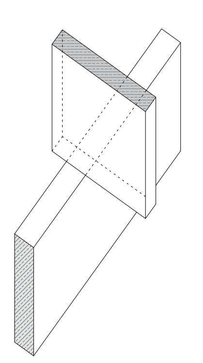
I have two perpendicular walls, one sitting on top of another (so the top wall is some sort of deep beam supported on an orthogonal wall). This is a quick sketch of the problem:
Both of the walls are 20 cm thick so their contact is relatively small. I made an STM model of the whole top wall (it has 2 supporting walls, this is a detail of one of them) and this is just a part of that model -a detail of the connection:
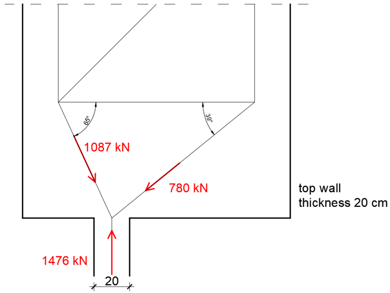
Now, of course, I know that it is better to divide the support force into two, one for each diagonal, but that is not important here. I also know that the left diagonal will probably fail here, but these are all things that I can find a solution to.
My problem is the contact point of the two walls, so the transfer of 1476 kN. What is the allowable pressure in your opinion? If I divide the force by area I get 36,9 MPa (1476000 / 200*200) - this is more than the design strength of 20 MPa.
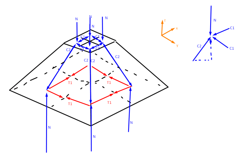
The question is does this need to be satisfied or can this stress be distributed to a larger area of the supporting member like in this picutre:
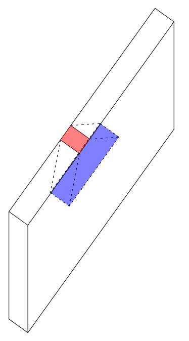
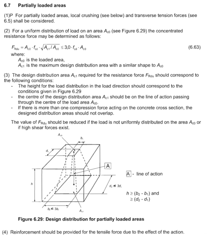
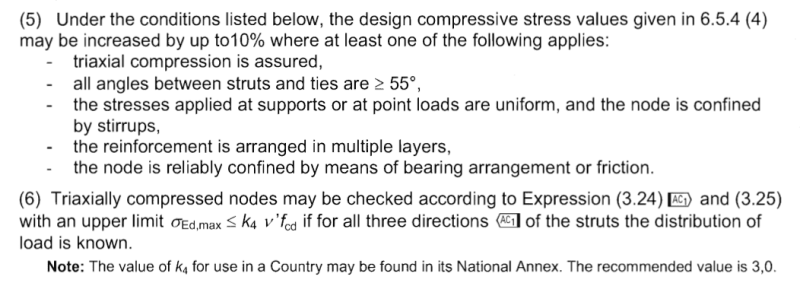
Eurocode has provisions for "partially loaded areas" where the strength increases by 2-3 times. This would help significantly in situations like these.
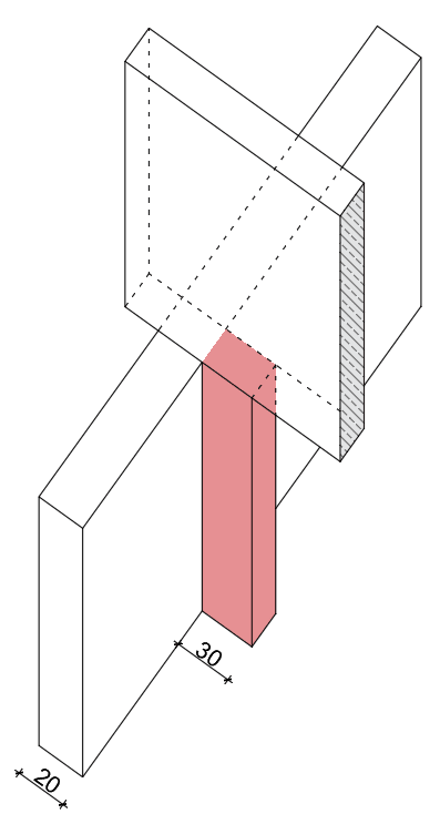
I know that I can always do something like the following picture to reduce the stress and it's certainly a better solution, but is it strictly necessary?
I have a question about STM and would like to hear your opinions.
I have two perpendicular walls, one sitting on top of another (so the top wall is some sort of deep beam supported on an orthogonal wall). This is a quick sketch of the problem:

Both of the walls are 20 cm thick so their contact is relatively small. I made an STM model of the whole top wall (it has 2 supporting walls, this is a detail of one of them) and this is just a part of that model -a detail of the connection:

Now, of course, I know that it is better to divide the support force into two, one for each diagonal, but that is not important here. I also know that the left diagonal will probably fail here, but these are all things that I can find a solution to.
My problem is the contact point of the two walls, so the transfer of 1476 kN. What is the allowable pressure in your opinion? If I divide the force by area I get 36,9 MPa (1476000 / 200*200) - this is more than the design strength of 20 MPa.
The question is does this need to be satisfied or can this stress be distributed to a larger area of the supporting member like in this picutre:

Eurocode has provisions for "partially loaded areas" where the strength increases by 2-3 times. This would help significantly in situations like these.
I know that I can always do something like the following picture to reduce the stress and it's certainly a better solution, but is it strictly necessary?


