Continue to Site

Eng-Tips is the largest engineering community on the Internet

Intelligent Work Forums for Engineering Professionals

  • Congratulations MintJulep on being selected by the Eng-Tips community for having the most helpful posts in the forums last week. Way to Go!

Straightness: parallel planar line element tolerance zone orientation 1

Status
Not open for further replies.

dtmbiz

Aerospace
Sep 23, 2008
292


Does anyone know of supporting documentation in: ASME Y14.5 or other professional training material for the orientation of this type tolerance zone other than "parallel to line element direction" in the view of the FCF as defined in ASME Y14.5 ?

Referencing a previous thread where the answer to a question was largely due to a claim that straightness control regarding a planar line element tolerance zone did not need to be oriented parallel to the line its FCF was pointing to.

Forum Thread 391408
In worst case, the flatness is...


I do not find any supporting documentation for the claim of "non" parallel tolerance zone orientation in the ASME Y14.5 standard , other professional training course material, or searches on the subject matter.

The ASME and other documentation does support that those tolerance zones do need to be oriented parallel to the considered line element "direction" relative to the view of the FCF.

REF: ASME

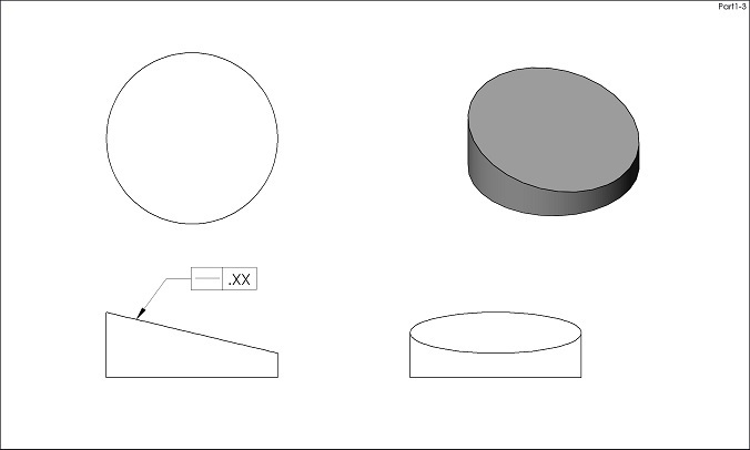
5.4.1.4 Straightness of Line Elements. Figure 5-6
illustrates the use of straightness tolerance on a flat surface.
Straightness may be applied to control line elements
in a single direction on a flat surface; it may also be applied
in two directions as shown. Where function requires
the line elements to be related to a datum feature(s), profile
of a line should be specified related to datums. See
Fig. 8-27.

 
Replies continue below

Recommended for you

From:

ASME Y14.5M-1994 Para. 6.4.1.1: “A straightness tolerance is applied in the view where the elements to be controlled are represented by a straight line”

ASME Y14.5.1M-1994 Para. 6.4.1.: “A straightness tolerance is applied in the view where the elements to be controlled are represented by a straight line”

ASME Y14.5-2009 Para. 5.4.1: “A straightness tolerance is applied in the view where the elements to be controlled are represented by a straight line”

I am not aware of any other interpretation.


"For every expert there is an equal and opposite expert"
Arthur C. Clarke Profiles of the future

 
dtmbiz,

Here is how I understand it. There are several steps involved - dividing the feature into planar cross sections, constraining these cross sections to the as-produced part, and optimizing each tolerance zone to its as-produced line element.

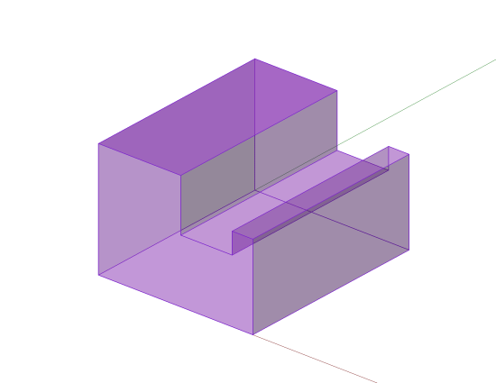
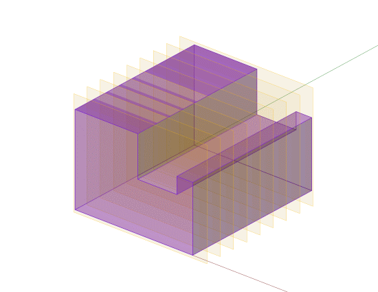
The first step is defining cutting planes that the tolerance zones exist in. The graphical indication (view direction) defines the orientation of these cutting planes relative to the rest of the theoretically exact part (model). The cutting planes are perpendicular to the view direction - the view is supposed to show a "side view" of the line element. Fig. 5-6 in Y14.5-2009 shows a part with two Straightness tolerances, in different directions. We know that the left-hand FCF chops the feature "cross-wise" into shorter line elements and the right-hand FCF chops it "lengthwise" into longer line elements.

The second step is applying this set of cutting planes to the actual as-produced part. This is where the ambiguity comes in. If the as-produced part has squareness error between the surfaces, we don't have a unique orientation for the cutting planes. In other words, we can't uniquely define the "cross-wise" direction. This is roughly similar to slicing up a loaf of bread that is parallelogram-shaped - do you make the slices parallel to the ends, or perpendicular to the sides?

The third step is optimizing the tolerance zones to their line elements. This is where the "non-parallelism" comes in. Once the cutting planes and tolerance zones have been defined, then the degrees of freedom can be applied. Straightness is a form tolerance and does not control orientation or location, so the tolerance zones are free to rotate and translate within their respective cutting plane. This makes each tolerance zone control only the straightness (form) of its line element, and not the relationship to other line elements, and makes it distinct from Flatness.

So the statement that a Straightness tolerance zone "does not need to be oriented parallel to the line its FCF was pointing to" is sort of true, but perhaps awkwardly worded. The zones are initially defined as being parallel to the line that the FCF is pointing to, but then do not have to remain parallel to it.

The fact that these subtle details are not clear is really not surprising at all. These things are very difficult to communicate clearly in words, as my long-winded explanation above demonstrates. Figure 5-6 in Y14.5-2009 is in desperate need of a "means this" figure.

Evan Janeshewski

Axymetrix Quality Engineering Inc.
 
axym said:
If the as-produced part has squareness error between the surfaces, we don't have a unique orientation for the cutting planes

Do you truly believe it will make any practical difference?

"For every expert there is an equal and opposite expert"
Arthur C. Clarke Profiles of the future


Axym

This the point I am getting to.
There is no specific mention in ASME Y14.5
This becomes a individuals interpretation.

CH
Absolutely a difference.
If the line element tolerance zones are interpreted to be parallel to the
line the FCF points to in a specific view, then in the thread mentioned, the
answer is no longer the size limits with 2 straightness controls.

This upload is from NCSU Engineering (Sht 1 of 2)

 
 http://files.engineering.com/getfile.aspx?folder=9c71357c-1852-43be-bf40-bd4d342f6417&file=Strght.4.jpg
There cannot be any specific mention.

Straightness is a FORM control, it cannot have a datum, it cannot be parallel to anything.

We are talking about orientation of section plane, that produces the line to be checked for straightness.

Axym is arguing that small variation in orientation of said surface will signifantly affect the result.

I disagree.

There is no disagreement that straightness tolerance zone is free to float following the surface variations.

"For every expert there is an equal and opposite expert"
Arthur C. Clarke Profiles of the future

 
Hi All,

This is excellent discussion. We're all kind of disagreeing, but we might all be correct ;^). I suspect that each of us is using the terms "orientation" and "parallel" in a slightly (or significantly) different way, to describe what we can see in our minds. The words are getting in the way, and we need pictures. Very detailed pictures. Lots of cliches apply here "a picture is worth a thousand words", "the devil is in the details", etc.

Don't worry, we will get to the bottom of this. But I have a couple of other things to take care of first, before I can devote more time to this. Possibly later this morning.

Evan Janeshewski

Axymetrix Quality Engineering Inc.


I agree with...


I probably disagree with...


Maybe you mean yourself and Axym... I disagree that the "surface" can float more than the largest tolerance zone of 2 straightness controls to the same surface. The controls must be applied simutaneously. The two straightness controls create "infinite" line element 2D tolerance zones that virtually create a 3D tolerance zone which the surface must line.

From what I read, Axym is coming from a point how he see's to measure straightness.

I would like to discuss "straightness" on the "intent" of the control.

I can think of no reason I would want to put 2 straightness controls in two different views to the same surface with expected results of a "warped" surface.

Again... what is the basis according to ASME Y14.5 for your interpretation that straightness of planar line element tolerance zones can be non-parallel relative to the orientation of the line that the FCF points to?

I cant alter my intrepretation of "parallel orientation", until someone guides me to the place that specifically states this.

In the absence of this specificity, I am basing the "intent" interpretation on basic English, engineering drawing interpretation and common sense.

Here is Webster's interpretation of straight:
Full Definition of STRAIGHT

a: free from curves, bends, angles, or irregularities <straight timber>


I do intend to place a straightness control on a planar surface to control some degree ; warp, curve, bends, angles etc. on that surface, beyond the size limit; not allow it to be "warped".


BTW, Axym.... I personally value your attitude "to get to the bottom of it", and I share it.

CH
I cant speak for you, however this thread my get to the point of highlighting why you have stated
that you dont see ASME as the language you would like to have. (my paraphrasing)

 
dtmbiz - what you are suggesting is that there is an implied parallelism to some other portion of a part. While this seems obvious on an item like a domino or brick, this won't apply to parts of noticeable complexity.

It isn't possible to have terminology or description as to what isn't applicable as there are an infinite number of those conditions. However, what is allowed is specified - all the form tolerances share this characteristic - they have no relation to any other feature of a part.

So far I've seen no parts where controlling straightness in orthogonal directions on a surface has any value, but a warped surface is an acceptable outcome if that is all that is applied.

 
This has always sort of bothered me. And I agree with Evan on all counts. CH, we say that form tolerance has no datum (which is true) but as soon as we chop the form tolerance into "each element" then we are automatically imposing some sort of reference plane (read: datum) for what direction these elements are to follow.
And it's not enough to say that it's merely in the direction of the viewing plane, because -- as Evan mentioned -- in the real world the various faces of a part might be out of orientation from each other themselves.

John-Paul Belanger
Certified Sr. GD&T Professional
Geometric Learning Systems
 
For what it's worth, I am with Evan on all counts too.

I just hope ASME will finally introduce a concept similar to ISO's Intersection Plane, as defined in ISO 1101:2012. This should solve the problem of inherent ambiguity when it comes to defining "a unique orientation for the cutting planes" (Evan) on a real part in case of straightness and profile of a line controls applied to a line element of a surface.


dtmbiz,

dtmbiz said:
Again... what is the basis according to ASME Y14.5 for your interpretation that straightness of planar line element tolerance zones can be non-parallel relative to the orientation of the line that the FCF points to?

Take a look at fig. 5-7 in Y14.5-2009. It is not about straightness tolerance, but flatness, however the logic is the same. Notice how the flatness tolerance zone looks like in the "Means this" part of the figure. It is not parallel relative to the orientation of the line the flatness FCF points to. This is absolutely correct, because flatness (and straightness) tolerance zone does not have to be parallel to anything.

Besides, even in the link to Al Neumann's materials you posted in one of your previous entries it is said that: "If the location or orientation of these tolerance zones is important, consider the use of profile of a line with datums". I think you will agree that this statement (which is by the way only a slight modification of the last sentence from para. 5.4.1.4 of Y14.5-2009 and para. 6.4.1.1.5 of Y14.5M-1994) clearly implies that for datumless straightness tolerance the tolerance zone is not located and/or oriented to anything.

By the way, perhaps you could provide an answer to SeasonLee's question in the thread "In worst case, the flatness is..."? Looks like the part in question has been taken directly from Neumann's book.
 
I have question to all experts on this thread:

Can we specify straightness on part like this?

Straight_orient_myljq6.jpg


"For every expert there is an equal and opposite expert"
Arthur C. Clarke Profiles of the future
 
@dtmbiz:

I took closer look at NCSU Engineering reference and I found it WRONG. For some reason they mixed pieces of straightness and flatness definitions together. I included reference to ASME Y14.5.1M to show the REAL definition.

About using Webster as reference for GD&T: Webster defines "parallel" as "everywhere equally distant" and gives example as "concentric spheres are parallel". Would you apply parallelism to concentric spheres just because Webster says so?

And finally, what is it with "...you have stated that you don't see ASME as the language you would like to have"? I only stated that proper language hasn't been created yet. Right now both ISO and ASME are more concerned about self-preservation, than serving the industry. Results are speaking for themselves.

"For every expert there is an equal and opposite expert"
Arthur C. Clarke Profiles of the future

 
 http://files.engineering.com/getfile.aspx?folder=c3fceff4-8df0-4c6c-b84a-bee55acd7a05&file=Flatness.png
Hi All,

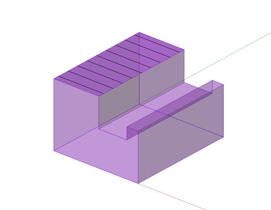
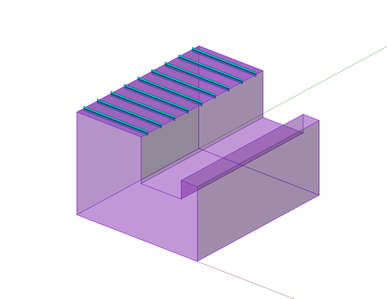
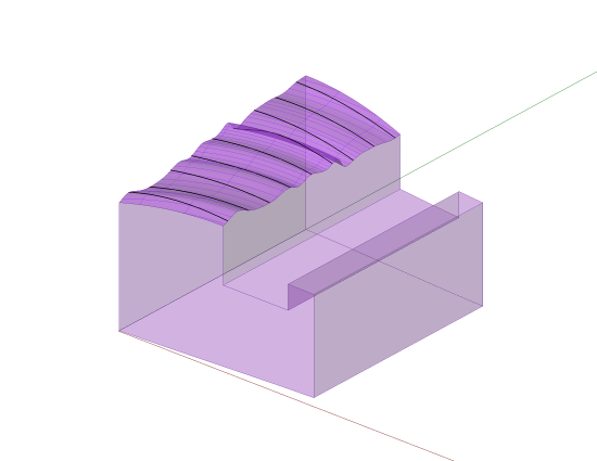
I've created an extended "means this" for Fig. 5-6 of Y14.5-2009, for the 0.05 Straightness tolerance. The following sequence shows the basic part, cutting planes oriented per the drawing view, basic line elements, and tolerance zones. Hopefully there isn't any ambiguity or disagreement so far, as we're still looking at perfect geometry and haven't gotten to the fun part yet.

L_Basic_Part_o2iwpp.png

L_Basic_Part_and_Cutting_Planes_vx62ox.png

L_Basic_Part_and_Basic_Line_Elements_lwjzy6.png

L_Basic_Part_and_Basic_Line_Elements_and_Tol_Zones_z5tvip.png


Evan Janeshewski

Axymetrix Quality Engineering Inc.
 
Hi All,

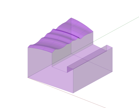
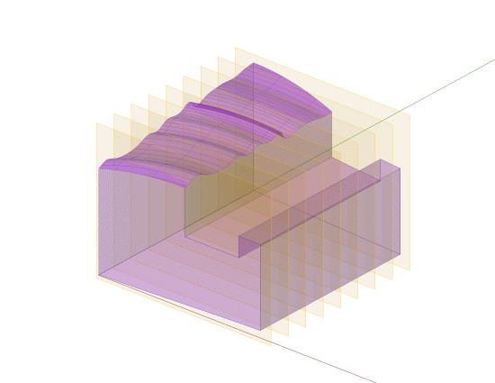
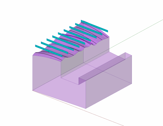
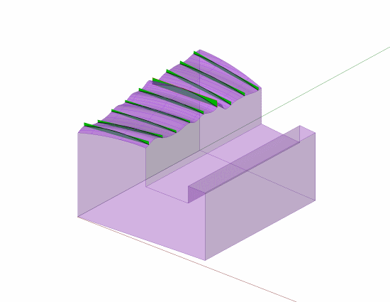
Now for the fun part - trying to apply this to imperfect as-produced part geometry. This is where the ambiguity comes in. I dreamed up an as-produced part with a wavy/twisted/tilted considered surface, and sides that are not square to each other. This will hopefully smoke all of the hornets out.

We section the considered surface into actual line elements, using the same cutting planes that the tolerance zones were defined in. Then we bring the tolerance zones back in, and each one gets individually fitted to its respective line element. Each zone must stay within its cutting plane (and thus stay parallel to the other zones in one sense), but can freely rotate and translate within the cutting plane (and thus not stay parallel to the other zones in another sense).

L_Act_Part_1_kbml5g.png

L_Act_Part_1_and_Cutting_Planes_s0mtnp.png

L_Act_Part_1_and_Act_Line_Elements_awuu9r.png

L_Act_Part_1_and_Act_Line_Elements_and_Tol_Zones_yppsyb.png

L_Act_Part_1_and_Act_Line_Elements_and_Act_Zones_dqdoe4.png


Evan Janeshewski

Axymetrix Quality Engineering Inc.
 

Thank you all for your responses,

As I read Axym's original response a few times, it is my understanding that you are basing the interpretation on how the control is actually measured? That's how I take it.
I actually do agree also EXCEPT for:

It reads to me that Axym is addressing the problems of measurement. It also reads to me that NCSU is using a "mating surface" to measure the straightness result.

Axym appears to have put substantial effort into showing graphically the non-parallel tolerance zones. Obviously well done. It also demonstrates why the produced surface surely does not result in the intent of straightness. I do not see a loaf of bread as straight. It certainly doesnt fit the English definition of straight. (Relative to geometry)

It is clear to me that ASME needs clarification because....

Are we not to apply GDT controls based on intent of function & assembly interface?

Not receiving any new information to refute the OP question regarding "required parallelism of tolerance zones" from ASME Y14.5 actually answers the question.

To date, there is no basis for strictly interpreting the "intent for straightness" for planar line element tolerance zones orientation, other than the ASME y14.5 statements for FCF’s being placed in the view where elements are controlled by a representative straight line & a single direction (2 directions if 2 views are used)

An important tool for my interpretation in addition to those I have listed originally should obviously be mathematical definitions. What is a direction? Does it say "multi directions" as non-parallel tolerance zones show?

This is why I base my interpretation for” intent of straightness” tolerance zones as parallel to the line (which defines the “direction” / vector) vs. how straightness may be measured. I probably would concede that a real part deviates from perfect and the tolerance zones arent't parallel to the perfect line, however they need to be oriented parallel to each other. Not varing "directions".
(Not just the cutting planes to each other as it reads to me Axym is eluding to: ..."in a sense"...)?

Description of a line
A line is a set of points extending in both directions containing the shortest path between any two points on it.

A Vector is something that has two and only two defining characteristics.
• Magnitude: the meaning of magnitude is 'size' or 'quantity'
• Direction: the meaning of direction is quite self-explanatory. It simply means that the vector is directed from one place to another.

From NCSU engineering posting: (I read this as supporting the interpretation that line element tolerance zones are oriented parallel to the line indicated to provide intended direction.)

Conformance:
A surface line element conforms to the straightness tolerance….
….A surface conforms to the straightness tolerance t0 if it conforms simultaneously for all tolerance surface line elements corresponding t some actual mating surface....


What if there is no "line indicated to provide intended direction"?

"For every expert there is an equal and opposite expert"
Arthur C. Clarke Profiles of the future

 
Status
Not open for further replies.

Part and Inventory Search

Sponsor