Continue to Site

Eng-Tips is the largest engineering community on the Internet

Intelligent Work Forums for Engineering Professionals

  • Congratulations MintJulep on being selected by the Eng-Tips community for having the most helpful posts in the forums last week. Way to Go!

Straightness: parallel planar line element tolerance zone orientation 1

Status
Not open for further replies.

dtmbiz

Aerospace
Sep 23, 2008
292


Does anyone know of supporting documentation in: ASME Y14.5 or other professional training material for the orientation of this type tolerance zone other than "parallel to line element direction" in the view of the FCF as defined in ASME Y14.5 ?

Referencing a previous thread where the answer to a question was largely due to a claim that straightness control regarding a planar line element tolerance zone did not need to be oriented parallel to the line its FCF was pointing to.

Forum Thread 391408
In worst case, the flatness is...


I do not find any supporting documentation for the claim of "non" parallel tolerance zone orientation in the ASME Y14.5 standard , other professional training course material, or searches on the subject matter.

The ASME and other documentation does support that those tolerance zones do need to be oriented parallel to the considered line element "direction" relative to the view of the FCF.

REF: ASME

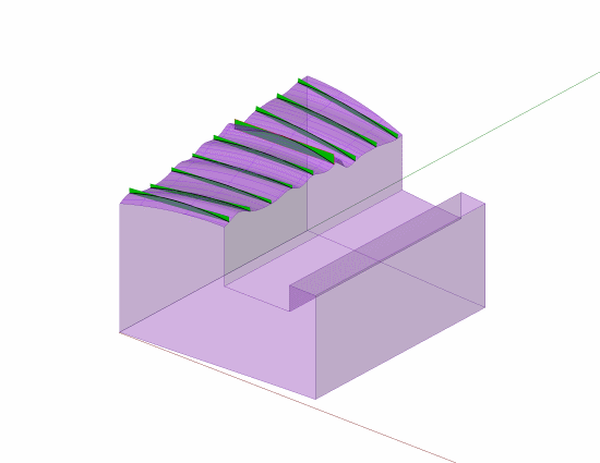
5.4.1.4 Straightness of Line Elements. Figure 5-6
illustrates the use of straightness tolerance on a flat surface.
Straightness may be applied to control line elements
in a single direction on a flat surface; it may also be applied
in two directions as shown. Where function requires
the line elements to be related to a datum feature(s), profile
of a line should be specified related to datums. See
Fig. 8-27.

 
Replies continue below

Recommended for you


If you are referring to the cylinder that was posted, I would create a section view
to show the line. Two sections at 90deg if 2 straight controls were needed.
 
dtmbiz,

How does a section of a drawing view create an orientation for the measurement of straightness on the wedged cylinder?

OTOH, how would the part be appropriately oriented without a feature that controls rotation about the cylinder axis?

Sometimes there are too few degrees of freedom controlled to make a meaningful interpretation. Unfortunately for straightness, unless there is an obvious axis of symmetry that entirely fixes the orientation of the zone, there doesn't seem to be a firm control.
 
To CH's question on the circular part: Yes, you can specify straightness in that way for that part. The part is not oriented by any "front," "back," or "side" face -- the only thing that can possible orient the part is the angled top surface. So we rotate the part until we get that top surface to appear as level as possible (not level in the left/right sense, of course, but in the front/back direction that you peer into. This is trying to eliminate parallax or whatever you want to call it.)
Then we slice up the elements and check each for straightness.

But that's very different than the examples we've been discussing, because yours has no other faces which could possibly be used to orient the part. So I don't see how your example would answer the prevailing question about Fig. 5-6 in the standard, which has multiple surfaces competing for the part's orientation.

John-Paul Belanger
Certified Sr. GD&T Professional
Geometric Learning Systems
 
Not sure why the NCSU explanation uses cross product for flatness. Seems like an evaluation that would use the dot product.

From "The dot product therefore has the geometric interpretation as the length of the projection of X onto the unit vector Y^^ when the two vectors are placed so that their tails coincide."

IOW, the method should subtract some base vector from all the point vectors and then find out how much from what is left over that is aligned with a unit vector normal to the tolerance zone; that amount should be less than or equal to 1/2 the distance between the limits.

Cross product is (often) for finding torque and for determining the orientation of the mutual normal, neither of which seems to match straightness verification.
Not sure how cross product would fit in.

The straightness diagram is also vague - so many individual dots identified as vectors, like vector A. I'm sure it all makes sense to someone, but it doesn't match vector diagrams I've seen before as explanations.
 
The diagrams with sections suffers from the same problem, an assumption as to the orientation of the cylinder, and is no different from orthographic projection.


3DDave,

What you see as “suffering”, I see as engineering drawing interpretation.

There are significant differences between the outer orthogonal view(s) and the section view,
even though in this case they look the same.

One section is a cutting plane thru the high point of the angled surface.
The high point is an actual vertex at the end of a “straight line segment”. The staight line indicates “direction” regarding the straightness control. The other section by interpretation is at 90 degrees to the 1st section. Again; "direction" for the straightness control.

If the control were pointing to the curve in the orthogonal view then the direction could possibly be unclear as that object line represents the curved arc shown in that view.

This was the intent of the section to satisfy an earlier post. I believed to be relative to “direction”.

The "high point" is irrelevant regarding the straightness control.

The drawing is incomplete and other delineation and annotation could be added to clarify concerns.

Measuring the part is different animal.

All,

I have never claimed to support the use of a straightness control on a planar surface. Not an advocate.

This for me has been about an interpretation of a straightness control, particularly regarding the tolerance zone orientation. The standard is weak on definition and needs clarification. However what is currently defined and/or implied is what there is to work with.

Why interesting to me? Because it impacts the answer to a question in a previous post. The “max flatness” question fits into the trivia category for me and is not of any practical use.

Thank you for your comments relating to the OP question.

 
In 5.4.1.4 a refinement is provided for in the last sentence.
Where function requires the line elements to be related to a datum feature(s), profile of a line should be specified related to datums.​

In Fig. 5-6, multiple options for setting up the part for inspection exist. As long as the part can be shown to conform in any one particular set up, it should be "case closed."

The complaint should be that the ambiguity of the callout requires the time consumption of multiple set-ups and checks to determine if there is one (or more) setup(s) that conform(s).

Arguably, the cylindrical examples allow for determining a direction based on the intersection of the two planes as one potential setup of the part for inspection.
 
dtmbiz,

Thank you for the comments on my figures. It's interesting how you saw them as being based on how the part would be measured - that wasn't quite my intent.

I think that the figures (especially the final one) show the result of applying the straightness tolerance to actual part geometry, but are not specific to a particular inspection method. This result could be accomplished using a number of different inspection techniques - open setup with dial indicator and surface plate, CMM, straightedge, or physical sectioning. Whatever technique is used must maintain the required constraints and degrees of freedom between the line elements (established using parallel cross sections) and the tolerance zones (also established using parallel cross sections but free to rotate and translate). For example, the non-parallel-ness of the tolerance zones allows the inspector to level the part individually for each indicator sweep if the open setup method is used.

Your interpretation that the zones must be parallel to the perfect line element, and therefore parallel to each other, is not one that I have heard before. I re-read your original post, and the text of section 5.4.1.4, and I believe that I now understand the basis of your interpretation. You are taking the phrase "to control line elements in a single direction" to mean that the tolerance zones must all be oriented in a common direction, and therefore the zones must be parallel to each other? Do I have this correct?

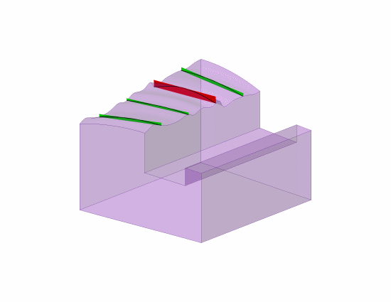
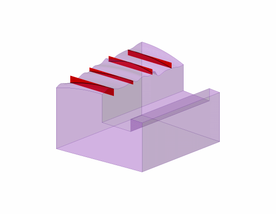
Here are more figures to illustrate the comparison. One interpretation is on the left, with zones that are individually fitted to each line element with no constraints (other than staying in the cutting plane). The other interpretation is on the right, with zones that are individually fitted but with the constraint that the zones remain parallel to each other. So the overall twist of the surface would not affect the straightness with one interpretation, but affects it with the other. Does this capture the issue?

L_Act_Part_1_and_Non-Parallel_Zones_bmez11.png
L_Act_Part_1_and_Parallel_Zones_mvljpk.png


Evan Janeshewski

Axymetrix Quality Engineering Inc.
 
Axym

Yes


Not quite

I have been ultimately and maybe not so clearly getting back to the "max flatness" question.
To effect the flatness with straightness would require 2 straightness callouts and they would need to be oriented parallel to the defined "direction". The line that the FCF points to would be the definer.

I agree with your models as shown with 1 straightness control, and that straightness can float within the
size limits whether the tolerance zones are parallel or not.

Now what do the tolerance zones look like if there is another straightness contol at 90 degrees?
This is where the parallelism comes in.
If they are not required to be parallel then straightness still has no effect on flatness.
If they are parallel oriented zones, then the tolerances zones you have shown will need to come within the crossing tolerance zones; which I contend will effect flatness beyond the limits of size.

BTW
Mark Foster of AGI commented to me that his understanding of the tolerance zone orientation is "view dependent".
That raises questions too ("view dependent")
I did not have time to emphasis the "direction" word in ASME and its impact in that discussion.
He basically called the ASME definition "weak". (posted above)
He also eluded to ISO and it's GPS mechanism to define the way the tolerance zones are oriented without a datum.
I dont have ISO. I deal with ASME.

Thank you for your efforts and time to discuss this and especially to consider where I am coming from !
Whether you agree with someone or not, IMO it is commendable to try to see "why" the person may have a different interpretation based on the same information.
Appreciated !!!


dtmbiz,

It sounds like we're on the same page (or at least on one of the same pages). We still don't agree on whether the straightness zones need to be parallel to each other or not, but I think we agree on the consequences of either case.

If the zones are required to be parallel to each other, and there are two straightness controls, then I think I agree that this combination would limit the maximum flatness error. But I'm not sure what the maximum limit would be - I'm not sure that it would be a straightforward combination of the two straightness values. I would also say that this combination would not require one set of zones to fall within the crossing set - it would just mean that the surface needs to conform to both sets of zones. This is a subtle distinction though.

Personally, I don't place much value in the "maximum possible flatness arror from other controls" discussions. If the designer needs the flatness to be controlled, they should be able to specify a flatness control and not rely on indirect controls. But Y14.5 makes us care about things like that, by disallowing geometric tolerances that are not a refinement of other tolerances that would limit the same characteristic.

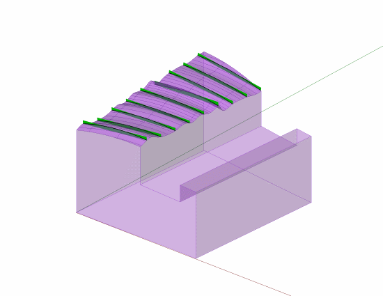
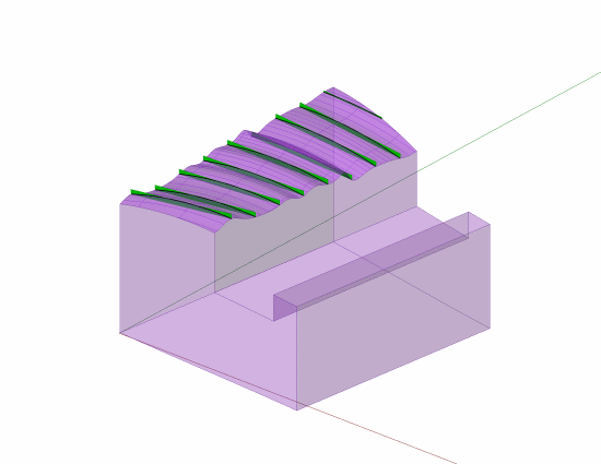
The tolerance zone orientation, in terms of being view dependent, is a separate issue. I wish that Y14.5 would explain this better. The thing that is view dependent is the orientation of the cutting planes, and this is what Mark is referring to with the "weak" definition. It's weak because we can't establish the "view dependent" direction for the cutting planes uniquely on a real part. I tried aligning the cutting planes three different ways - perpendicular to the left-hand face of the part, parallel to the front face, and best-fitted to the considered surface. Here is what the results look like:

L_Act_Part_1_and_Act_Line_Elements_and_Act_Zones_ys58h2.png
L_Act_Part_2_and_Act_Line_Elements_and_Act_Zones_xap4dh.png
L_Act_Part_3_and_Act_Line_Elements_and_Act_Zones_refbuj.png


The measured value of straightness, which would be the width of the largest of the fitted zones, is different for each case. This is because the faces of the part are not square to each other, and the "lay" of the surface is not square to the faces. Because the current definition does not specify how the view direction is established on the as-produced part, any of these three possible cutting plane orientations is allowed (as well as many others). As Mark mentioned, the ISO GPS standards have additional symbology to align the cutting planes to specific features on the part. Before you say it, CH, in most applications there would not be an appreciable difference but in certain applications there might).

Evan Janeshewski

Axymetrix Quality Engineering Inc.
 
Evan, for what my 2 cents are worth, it wouldn't have occurred to me that anyone could see the straightness tolerance zones as NOT being parallel to each other! Taking that approach really throws a wrench into the standard's already-weak presentation of the topic.

John-Paul Belanger
Certified Sr. GD&T Professional
Geometric Learning Systems
 
Axym said:
Before you say it, CH

Am I allowed to say something else then?

I think we all agree that to be completely sure, we have to take infinite number of measurements. Which we never do.

We arbitrarily pick number of section planes and their location. If I take part in your example and draw my planes right between yours the difference in measurement may be at least same order of magnitude as from angular variation.

But nobody has problem with that.

Also, part has to be optimized - adjusted to reduce the effect of surface being inclined. In fact, part has to be optimized for every measurement independently. The method is not perfect, merely our "best effort"

No problem as well.

But may I suggest we arbitrarily optimize the direction of our cutting planes as well?

Fol example, the surface in question has marks from planing. Will it make sense to take measurement along the marks or across them? (I think that's the only good reason to specify straightness in two perpendicular directions anyway - to control the shaping marks :)).

So let's be consistent - either we are allowed to make reasonable "optimizations" or not.

"For every expert there is an equal and opposite expert"
Arthur C. Clarke Profiles of the future

 
John-Paul,

I'm assuming that you mean parallel to each other in the sense that the cutting planes are parallel to each other. Not in the sense that dtmbiz is contending. But I'm not sure ;^).

This is why the words fail us - the zones can be parallel to each other in one sense, and not parallel to each other in the other sense.

In my post from 17:08 Sep 23, there are two figures. The left-hand figure has three green zones and one red zone, and the zones are parallel to each other in one sense and not the other. The right-hand figure has four red zones that are parallel to each other in both senses. Which figure do you think is correct?

Evan Janeshewski

Axymetrix Quality Engineering Inc.
 
Evan,
Yeah, maybe I wasn't following the wording too closely, but here's what I meant: The planes that we slice up to check the straightnesses must all be parallel to one another. The zones within each slice can rock/rotate all they want, as long as they stay within those cutting planes.
So of the two pictures you posted at 17:08, I think I'm agreeing with the first one (with the green zones).
My beef remains this: to what surface on the part should those cutting planes be oriented? I wasn't following the other comments in this thread much because this simple ambiguity is enough for me to blow off the entire idea of straightness applied to a flat surface.

John-Paul Belanger
Certified Sr. GD&T Professional
Geometric Learning Systems
 
CH,

I think I agree with all of that.

We are allowed optimize the direction of the cutting planes. There are no datum feature references for straightness tolerances, so we can pick any direction we want for the cutting plane orientation. The "view direction" indicates a direction for the planes to be normal to, but there is nothing specific to establish this on a real part. So I agree that the cutting plane orientation can be optimized - this is what I tried to do in the third example in my post from earlier today. The cutting planes are parallel to the marks from planing, as you say. This gives the best (lowest) measured value for straightness.

After a cutting plane orientation has been chosen, I also agree that the part can be optimized for each line element measurement independently (this is where dtmbiz and I disagree).

Evan Janeshewski

Axymetrix Quality Engineering Inc.
 
The orthographic projection also shows a high point and a low point. The section makes no difference. You could have created a true view of the elliptical top surface and, in one view, drawn the direction lines for the straightness tolerance.

In an actual part there could be multiple points of identical height and they may not be diametrically opposite any of the lowest points; the section fails to clarify the correct orientation to be chosen to measure those characteristics.
 
John-Paul,

That's what I thought you meant. Your description of the zones agrees with my understanding.

Your remaining beef relates to the other issue that CH just mentioned, of how to orient the cutting planes to the part. I believe we're all in agreement that there is no unique way to establish the "view direction" on a real part, giving us the ambiguity. In other words, the degrees of freedom between the part and the cutting planes are not constrained. Where there is no constraint, we are allowed to optimize.

Evan Janeshewski

Axymetrix Quality Engineering Inc.
 
Status
Not open for further replies.

Part and Inventory Search

Sponsor