Celt83 said:
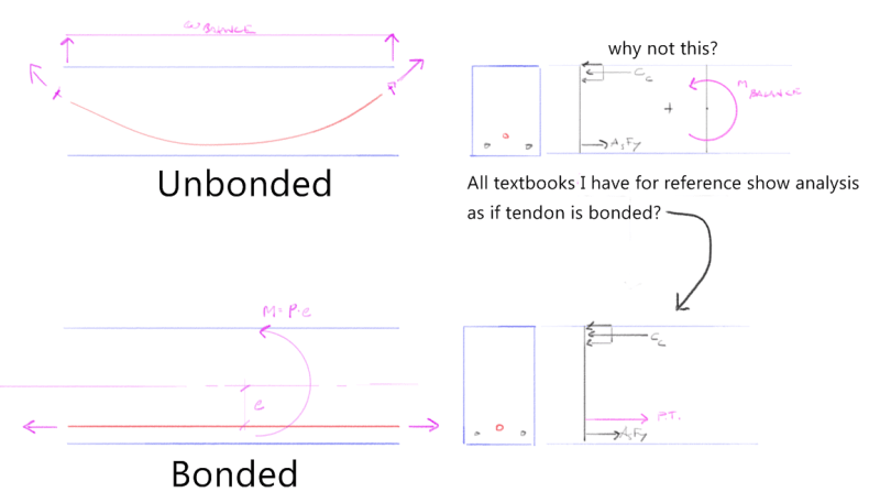
This is likely a dumb question but it has puzzled me a bit, all the reference texts I've seen on the subject show the tendon force applied at the tendon elevation in the cross section for the strain compatibility analysis. What I have trouble wrapping my head around is that in an unbonded system there is no bond so shouldn't the strain analysis only consider the stress block, steel, and the balance moment at the cross section in lieu of the PT force * distance to the neutral axis?
Celt83 said:
Reality is phi*Mn >= Mu,factored applied loads + M,hyperstatic but in my head I want to do phi*Mn >= Mu,factored applied loads + M,hyperstatic - M,balance. If I did what's in my head vs what I write then my check on the moment would be double dipping on the balance force.
It sounds as though you've got this sorted now, probably from
several angles. That said, I believe that I went through almost the exact same pain in a previous thread where rapt's input was instrumental in helping me get things sorted out:
Link. I thought that you might benefit from hearing the story told from my perspective and from examining some of the sketches that I developed to help me get my ship righted on this.
OLD KOOTK QUESTION:
In the ultimate flexure calculations, you always see the PT force placed at the level of the PT. How did it get there given that it started off at the end anchorage elevation and, in unbonded PT, there is no mechanism for the transfer of "bond stress" between the tendons and the surrounding concrete? No bond equals no strain compatibility, right?
NEW KOOTK UNDERSTANDING:
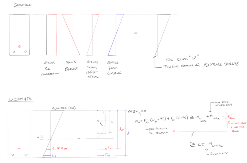
In draped PT beams, flexural resistance can/must be considered to be coming from two, independent but related sources:
1) The effect of the axial pre-stress acting alone and reducing cross section demand for tensile reinforcing.
2) The balancing load effect from tendon curvature effectively acting as a transverse loading on the concrete member to counteract external loads.
It is true that the balancing load can only be counted once, and I've stumbled on that myself in the past. However, it is also true that the balancing load effect is an integral part of the flexural resistance in a post-tensioned beam with drape.
The big takeaway for me considering the original question (read it again now for good measure please):
The applied PT force really has not moved from the elevation at which it originated at the anchorages. For flexural analysis, the unbonded PT force can be placed at the level of the tendons at any cross section because what is actually being represented is the summation of effects #1 & #2, described above. The balancing force stresses are essentially replaced by an equivalent, faux eccentricity to the original anchorage forces. And the net effect is just as rapt has described: P x e.
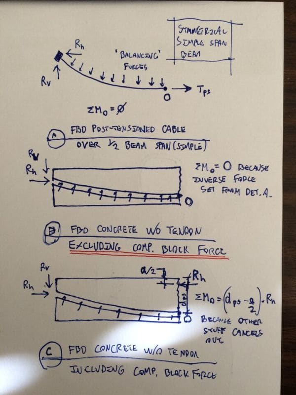
The first sketch below is my examination of the situation considering the tendons and the concrete as separate members, each acting upon the other appropriately. For some reason, I find that presentation a great help to my understanding.
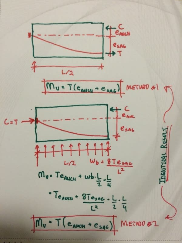
The second sketch is me using two different methods to determine flexural capacity, proving that both are valid and just different sides of the same coin:
A) Conventional P x e where the balancing load effect is buried in the "e" value.
B) An alternate formulation where the balancing load effect is considered explicitly.
I've got my fingers crossed hoping that I've added something meaningful to the conversation here for you. Otherwise, I'll have wasted a good chunk of football Sunday for nothing! Ah well, all investments are risks.
Note that most of what I've described and sketched is for simple span beams. Things get a bit more complex when secondary effects associated with continuity etc are considered. I've done things as I have not because I don't recognize that complexity but, rather, because the added complexity tends to obfuscate the truth of the points that I've tried to make.