ZeroStress
Structural
Hello and thanks for your valuable advise.
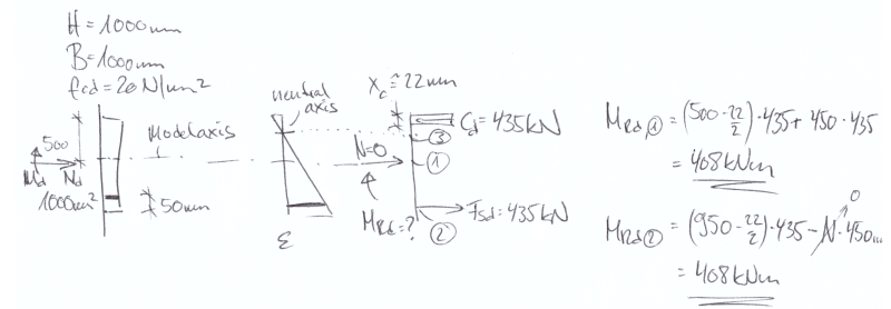
I am struggling with something that has been bothering me for a while. This is regarding finding out the ultimate bending resistance of a rienforced concrete section. I have attached the hand calcs.
The concrete section in the question already has an axial compression load of 300kN. In my first iteration of x=466mm, I have not been able to balance the section and hence it needs another iteration for the neutral axis depth "x".
However, my actual question is the way I am calculating the bending resistance of the section. Lets say that the equilibrium of the section has been achieved at x = 466mm as in the calcs.
In order to calculate the bending resistance of the section, is it correct to multiply each force with its lever arm as in the "Stress Diagram" figure?
The reason I am asking this question is that I have used AutoDESK Structural Bridge Design software for the same section and the way it calculates the bending resistance is it multiplies each force with its lever arm measured from the centroid of the force to the farthest "opposite stress" fibre.
For example, ASBD software would multimply:
Fsc with lever arm of 732 - 63 = 669mm
Fcc with lever arm of 732 - 186.5 = 545mm
etc
This gives very different bending resistance. Could anyone help please. Thanks.