Continue to Site

Eng-Tips is the largest engineering community on the Internet

Intelligent Work Forums for Engineering Professionals

  • Congratulations KootK on being selected by the Eng-Tips community for having the most helpful posts in the forums last week. Way to Go!

Strain gauge drift?

Status
Not open for further replies.

Bicky22

Mechanical
May 15, 2014
58
Hi,

I am having some difficultly with a strain gauge measurement and I am looking for some insight.

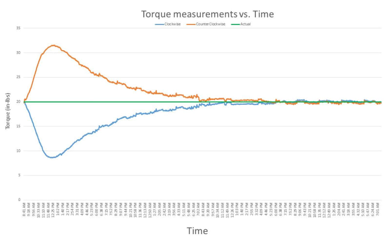
In a torque application, I see a drift with my strain gauges (2 half bridges on opposing sides of the shaft). I am calibrating them using 2 known points to create a calibration line. It appears that over time the 0 point of that calibration curve will shift, but then also return to 0 after about 24 hours. See actual measurements below. This graph shows ~15,000 measurements taken over ~48 hours where it was calibrated at the beginning. I am not sure why there is a drift and then a drift back.

Setup information:

Shaft:
0.5” diameter 4140 shaft heat treated to 53HRC

Environment:
Elevated temperature environment: ~ 135 F

Adhesive:
Pemabond 820 High temperature Cyanoacrylate

Stain gauge:
Steel compensated.
2x Half-bridge Strain Gauge
1 kΩ per quarter-bridge
3 mm active length

Excitation voltage: 5VDC with dc meter
Torque_Drift_k1xtis.jpg
 
Replies continue below

Recommended for you

Have you considered trying a quarter bridge circuit? Also, what resistance gauges are you using?

Drift might be related to elastic rebound in adhesive


How long has the system been bonded and hot before you start measuring?
How stable is your temperature +/-2F? What is the temp coef or your bridges?
Have you thermal cycled the shaft for stress relief?

= = = = = = = = = = = = = = = = = = = =
P.E. Metallurgy
 
What do the next 96 hours look like?

You'd like to think that the bridge was reasonably well temperature-compensated - with all four quarters being made from active elements that are stuck onto the same lump of metal.

The other bit of the equation is your measuring instrument. I wonder if that finds itself in a changing environment (your 48 hours weren't a Friday and a Saturday were they?)

A.
 
how are you collecting so much data, thousands of data points (different torques) over 48 hrs ?
and each zero point is based on two measurements ?

Are you applying two torque levels (mechanically, repeatedly) and calculating zero on two results ?
(ie 1st between 1 and 2, 2nd between 2 and 3, 3rd between 3 and 4, …)

another day in paradise, or is paradise one day closer ?
 
Ron:
I am not convinced a quarter bridge would be suitable for an elevated temperate torque application.
1 kΩ per quarter-bridge, the gauge is linked above.
I am not sure if it would classify as elastic rebound as the zero point seems to drift back.

EdStainless:
How long has the system been bonded
At least 96 hours.
hot before you start measuring?
It was not hot before I started measuring, it was calibrated cold. Ambient temperate would have rose to the ~ 135 F within a half an hour of beginning measurements. The shaft that the gauge was bonded too likely took a few hours to reach steady state.
Maybe the shaft temperate has something to do with the peak drift (min/max) valves I am seeing?
How stable is your temperature +/-2F?
~ +/- 10 F
What is the temp coef or your bridges?
Unsure. I can’t find the actual value, beyond it being listed as compensated for 4140 steel.
Have you thermal cycled the shaft for stress relief?
No. I did not specify the hardening process so I am unsure how it was performed at this time.

zeusfaber:
What do the next 96 hours look like?
I will let you know....

You'd like to think that the bridge was reasonably well temperature-compensated - with all four quarters being made from active elements that are stuck onto the same lump of metal.
I agree, that is why I am here soliciting advice.

The other bit of the equation is your measuring instrument. I wonder if that finds itself in a changing environment (your 48 hours weren't a Friday and a Saturday were they?)
I had thought about the measuring equipment, however I isolated the issue to the meter and gauges listed above. That is why I left information about the DAQ out of the post.
It was a Wednesday morning to Friday morning. What are you thinking with Friday and Saturday?

rb1957:
System was only calibrated once at the beginning by applying two torque levels and calculating zero on two results.

Data was taken by applying a known torque in both directions and measuring it with a DAQ. I have no indication and find it extremely unlikely that the DAQ is an issue. I have isolated the issue to the meter and gauges listed above

IRstuff:
Adhesive has been bonded for at least 96 hours, nor am I sure that a poor bond would cause a drift then a drift back as shown.
 
I'm at a loss for great ideas on this as the basics seem to be well enough covered. The main thing I would consider is that the support for the shaft has a lot of thermal mass and is applying a load as it came to temperature but without a picture of the setup it's just a guess.
 
3DDave
I wonder if you are on to something here, there is some mass to the setup.

To clarify your premise:
[ul]
[li]We have a Steady-state temperature at Time = 0 and Time = infinity, where Temperature of the shaft = Temperature of the strain gauge. This would mean no shift in calibration since the gauges are temperature compensated, everything is A-Okay.[/li]
[li]However; if during a non-steady state, Temperature of the shaft != Temperature of the strain gauge, a load would be applied to the gauge.[/li]
[/ul]

I agree with the overall principle, and further the data seems to correlate.

So for the heat transfer question…

The strain gauge is attached to the shaft with high temperature adhesive (linked above) and has some electrical tape around it as well for protection.

Let’s say the change in ambient air changes much quicker than any change to the shaft temperature due to thermal mass.

Would it make sense that we actually see temperature differential between the shaft and strain gauge during a heat up phase? My thought is yes, but I would like some others input on it.
 
Also, thank you to everyone. I do appreciate the help.
 
How is the bridge powered and the gage biased, i.e., is it continuously biased or intermittently biased; the time scales are too long, but I am curious about that.

TTFN (ta ta for now)
I can do absolutely anything. I'm an expert! faq731-376 forum1529 Entire Forum list
 
IRstuff
5VDC with the meter linked in previous post.

Every 10 seconds or so it takes about 25 measurements and logs the average which is shown in the graph. Actual value should be at 20. One load direction rises where one falls uniformly, indicating a shift of the 0 load calibration point.
 
Is this shaft in an oven? Forced convection?
I am sure what you see is the surface heating faster than the whole shaft.
If you extend this another week I wager that you will just see some minor ripples.

= = = = = = = = = = = = = = = = = = = =
P.E. Metallurgy
 
The Friday-Saturday guess was about the ambient temperature in the area where the meter is located - I was wondering if the building was heated during working hours on the first day, then cooler over the next 36+ hours as the weekend wore on.

Is everybody else generally happy with that meter providing the bias for the bridge? I'm just used to seeing something a bit more specific to strain gauging forming the first point of contact with the bridge.

A.
 
EdStainless
The shaft is just below an oven/heating elements. Free convection.
I do not wish to wager against you, I do not want to lose. I think you are right.

zeusfaber
I like the thought process but the temperature of the meter wouldn't stray far from room temperature. Further I find it unlikely the meter is an issue here. I actually have had excellent success with that meter in the past. I have about 15 of them. I would recommenced them; they are versatile, quick response time, isolated output, and cost effective compared to some others.


My plan is to look over the data on Monday to see what happened over the weekend. Then let the whole system cool for 24 hours and repeat the temperature ramp up again to see if the drift duplicates itself during the heating phase.
 
Status
Not open for further replies.

Part and Inventory Search

Sponsor