Continue to Site

Eng-Tips is the largest engineering community on the Internet

Intelligent Work Forums for Engineering Professionals

  • Congratulations cowski on being selected by the Eng-Tips community for having the most helpful posts in the forums last week. Way to Go!

Strain relation in a cylinder - strain gages 1

Status
Not open for further replies.

Mateus_R

Mechanical
Mar 15, 2018
48
Hello everyone,

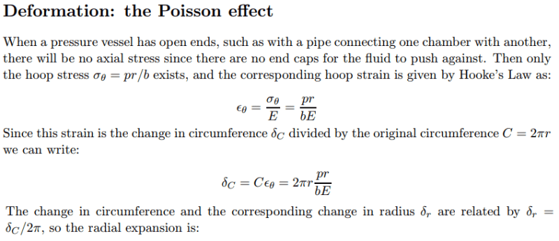
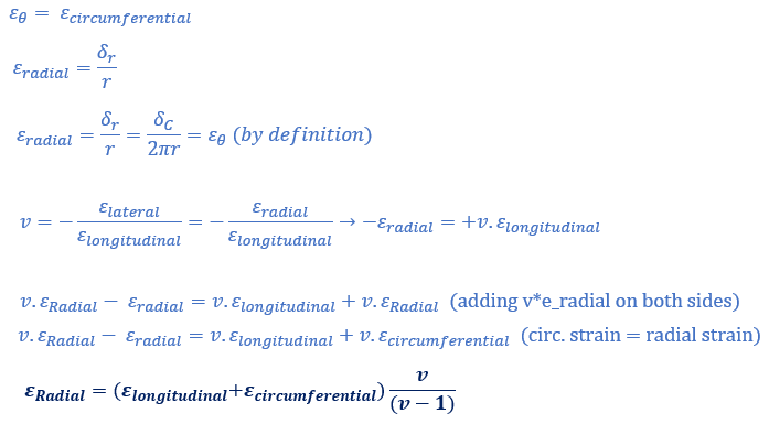
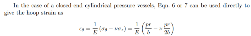
I'm analyzing how to measure the strains and obtain the stresses at a pipe using a strain gage (measuring circumferential and longitudinal strain with a rosette), and I was informed that the relation between radial strain and the other two components is the following one:

radial_strain_oscv5t.png


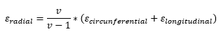
Someone knows from where this relation comes from and how to derive it?

Thank you.
 
Replies continue below

Recommended for you

Thank you @1503-44

From the paper, I understood that the strain equation I mentioned it is just math manipulation. I still don't understood why to use this equation, once I could apply directly the poisson definition and get it directly, since the circumferential strain and the radial one are the same .

deformation1_fohkxt.png


rearranging:

deformation2_dgjf4j.png
 
how does pressure play into this ... with hoop stress and axial stress ?

another day in paradise, or is paradise one day closer ?
 
rb1957, I'm not sure if I get you point, but the relation between hoop strain and pressure, considering the contribution of axial stress is given by:

image1_nwqfwa.png

from the link provided by 1503-44.

In this case seems that they are considering a plane stress state and later on calculating the radial strain as a consequence of hoop strain.
I found a generic relationship between Stress-Strain for a cylinder that accounts in the same equation for longitudinal, circumferential and radial:

image2_ymbih7.png


In my opinion, for a cylinder the approximation by the plane stress makes sense. Sincerely, I'm not sure if in this case it is correct to use this generic relationship that considers the 3 strain components.
 
The circumferential strain and radial strain are not the same. I think you noticed that the pipe diameter increases proportionally to the circumferential strain so that's why you made that assumption, but it is not correct. Radial strain results in the thickness of the walls of the pipes changing, not the diameter changing.

For thin walled pipes, you have circumferential and longitudinal stress and a negligible amount of radial stress that is assumed to be zero. This means your strains in each direction are:
ε,longitudinal = σ,longitudinal/E - ν*σ,circumferential/E​
ε,circumferential = σ,circumferential/E - ν*σ,longitudinal/E​
ε,radial = -ν*σ,circumferential/E - ν*σ,longitudinal/E​

Solving these equations will give you ε,radial = ν/(ν-1)*(ε,longitudinal + ε,circumferential)

Structural Engineering Software: Structural Engineering Videos:
 
I also have a problem with that model. What pressure vessel has open ends?
And fluid in a pressurized pipe connecting two chambers together pushes against the fluid in the chambers, which in turn push against all walls in the chamber, which in effect forms "chambered end caps". A pipe's internal pressure does not care if there is a blind flange or a chamber fixed to its ends, but if there is no resistance to a pipe's internal pressure at the pipe's ends, nothing attached, how can a pipe retain any internal pressure at all. The fluid would simply flow out the ends and internal pressure would be zero.

In a very long pipeline, the pressure at one end is the inlet pressure, say 100 psig. The pressure at the outlet 1000 pipe lengths away is 10 psig, because of friction generated by flow in the pipe. The friction is transferred to the pipe wall by viscous forces, thus the pipe wall stress (Poisson stress) gets carried down the pipe, some resisted by soil embedment forces, and eventually what's left of that combines with the fluid pressure at the outlet, to push against whatever pressure the fluid has at the pipeline's final exit conditions. There is in reality no "open ended pipe" anywhere that has no resisting pressure at its outlet, unless the pipe empties into a complete vacuum, 0 psia, but even that just means that the pipe wall stress plus internal pressure also equalled zero when precisely as it gets to the end of the pipeline.

You might want to see this too and read Wiki for Bulk Modulus and Poisson ratio.
 
@Mateus_R,

thank you you made my point. the 2nd post etheta (pointing to 1530-44's link, which I didn't open) is different to the first post you sent (where, under "deformation - the Poisson Effect" you have etheta = pR/bE).

another day in paradise, or is paradise one day closer ?
 
@rb1987, yes, the situations are different (PV with closed or open ends) and that's why the etheta changes:

1st post) a pressure vessel with open ends, considering no axial stress.

2nd post) a pressure vessel with closed ends, taking into account also axial stress contribution.

In any case, if you check the document provided by @1503-44, everything is well explained. Also in his last post there is some information about this open ends pressure vessels.


ok, it'd be nice to explain how you're using a pressure vessel with open ends ? maybe this is an assumption you make from pipework (as opposed to "proper" pressure vessels) ?

but then your first post derived your desired expression from the open ends assumption,
and your second post ... didn't ?

another day in paradise, or is paradise one day closer ?
 
@rb1957, the question from my first post was answered by @ProgrammingPE, with the assumption of thin pipes.

The remaining discussion comes from the article provided by @1503-44 that was followed by my 2nd post with the general relation between Stress-Stain for a cylinder.

Hope it is clear now.
 
Status
Not open for further replies.

Part and Inventory Search

Sponsor