Eng-Tips is the largest engineering community on the Internet

Intelligent Work Forums for Engineering Professionals

  • Congratulations waross on being selected by the Tek-Tips community for having the most helpful posts in the forums last week. Way to Go!

strange centerline dimension tolerance

Status
Not open for further replies.

sendithard

Industrial
Aug 26, 2021
166
0
0
US
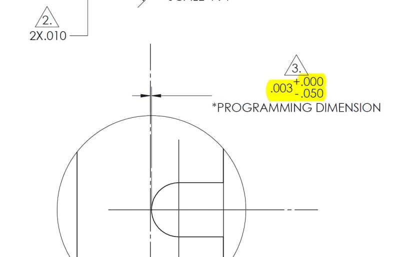
Is the yellow in the image saying the slot outer surface must be within .003 from the the part centerline, but is then also allowed to *extend past the centerline into the negative x direction by .047? Haven't seen this before.

Could this be simplified to a tolerance from the centerline somehow? I got confused on how construct this to be honest. If you went from the centerline can you say +.003 | -.047. Is this legal to assume right is positive, left is negative, I assume not so I got confused how to make this better.

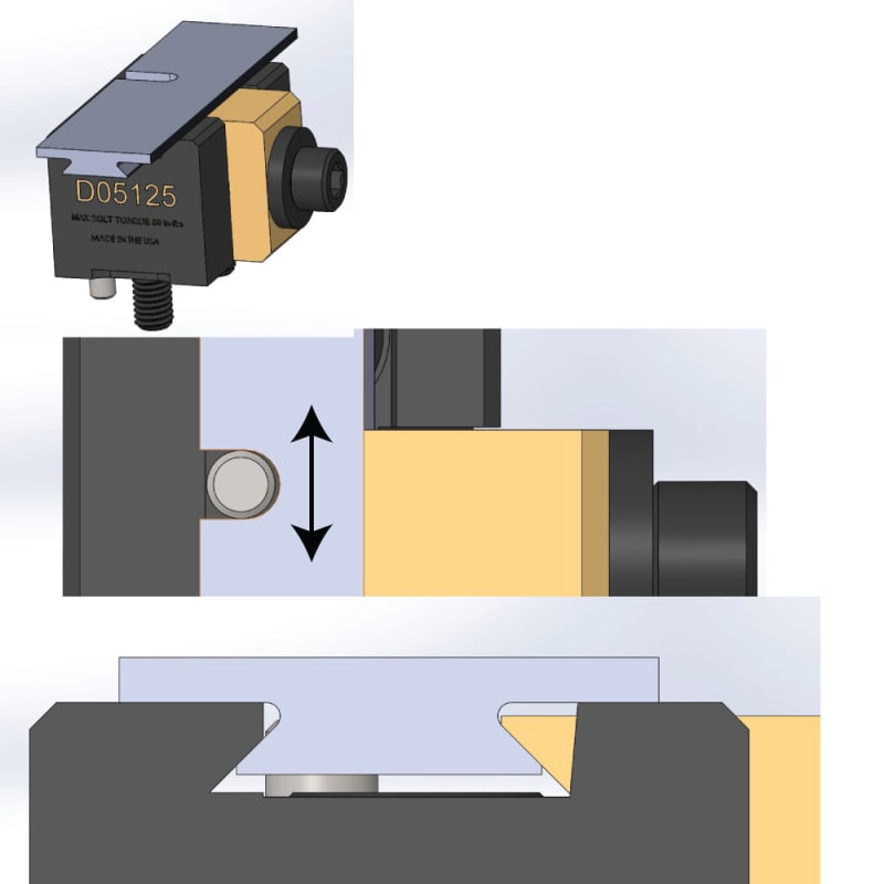
Appreciate your thoughts as always. The product and pdf is below:

Capture_bkt7hv.jpg
 
Replies continue below

Recommended for you

It appears to me to be a very creative way of ensuring the end of that radius doesn't cross the center of the part.

Just my opinion.

John Acosta, GDTP Senior Level
Manufacturing Engineering Tech
 
If it's a "programming dimension" then I'd assume the tolerance for the physical part is not shown in your picture. However, that doesn't seem to be the case according to the drawing.

Per the note, the dimension cannot be "too large" which per the drawing would mean further from the centerline -- (although it would also imply that -.010 isn't "too large" since the magnitude is negative). If it's NOT critical that the slot terminate before the centerline and indeed can pass over the centerline then this is a very odd way of going about it--as the machinist why would I target that nominal when I have a huge window to the other side of the centerline?
 
I've seen the one-sided tolerance used this way so as the machinist is working on the slot he first will hit the one value. If he's short of that he cuts more. If he goes over he has the full tolerance as a landing zone and he knows one end without the potential of making an error in addition or subtraction.

Find the center line with the tangent to a plug gauge that matches the cutting diameter; back off the .003, set the digital reading to zero. Replace the gauge with the cutter. Then the machinist has a clear -0.050 wide target zone.

One alternative is draw the notch as going over the center line by .022 and use a +/-.0.025, making the machinist responsible for figuring out both limits, when it looks like the goal is to be be stopped short by no more than. 0.003 and accept up to 0.050 clearance on the end.
 
sendithard,

What is a "programming dimension"?

I am satisfied that I can interpret your dimension. Is your diameter accurate enough to provide a good datum for measurement? If this were my part, I would call up a profile tolerance.

--
JHG
 
sendithard,

I am still thinking about your problem.

Which feature is generating your centre line? This is one of the problems with [±][ ]tolerances. Identify a datum feature, and call it up with a profile tolerance. Any feature that generates a centre line is a feature of size. If the feature of size is not accurate, you need to think through the implications of MMC/MMB on your profile tolerance.

--
JHG
 
If the nominal were .01 instead of .003 you wouldn't have any question would you?

You're over-thinking it because the arithmetic produces a negative number.
 
I agree with drawoh and Chris that it is ambiguous as to which direction the negative tolerance would apply without knowing from which side the dimension originates. [ponder]
Profile can be your friend.

"Know the rules well, so you can break them effectively."
-Dalai Lama XIV
 
This isn't my product, I was looking at it to hold some stock to be machined. The stock needs to be cut with a dovetail to the specific dimensions in the drawing.

I had time just now to model up the stock dovetail portion per the nominals on the drawing. It appears that the design intent is to allow the slot to breach past the centerline. If you allow the tolerance to go the other way the locating pin in the fixture that the dovetail slides in will interfere. The locating pin just prevents sliding inside the dovetail show in arrows below. It shouldn't touch the radius portion of the slot walls.

Below is the nominal fit picture assembly. I believe the feature of size that would be creating the centerline would be the width of the dovetail .413 as seen in the last pic. I have no idea what programming dimension is.

Is a negative plus minus dimension like this allowed with the standard. It was confusing which way the negative tolerance was going until I modeled the assembly and saw it could breach the centerline.

Untitled-2_xoz2ac.jpg

fos_ohnkhr.jpg
 
Status
Not open for further replies.
Back
Top