Continue to Site

Eng-Tips is the largest engineering community on the Internet

Intelligent Work Forums for Engineering Professionals

  • Congratulations GregLocock on being selected by the Eng-Tips community for having the most helpful posts in the forums last week. Way to Go!

Strange current imbalance on pumps

Status
Not open for further replies.

triden

Electrical
Jan 21, 2020
3
I have a system with some submersible pumps that are fed by some Siemens Sirius soft starts. Pumps are 125HP @ 600vac. When we run the pump, the softstart gets up to speed like normal (5s ramp) and the bypass contactor pulls. Within about 10 minutes they start overloading and tripping (some trip within 30 seconds). I checked the current on each leg on the load and supply side of the starter and get the following readings:

L1: 119A
L2: 151A
L3: 128A

Quite the imbalance. Just for the fun of it, we swung the transfer switch over and ran the station on genset power. All phase currents were perfectly balanced with no issues. Pumps didn't overload or trip and were very happy.

Swung back to the utility and major current imbalance again. Measured phase to ground on each leg and got within 5vac which is very close...so doesn't seem like a voltage issue. The problem is the same for all pumps in the station.

Anyhow, power company came up and said everything was fine. Clearly it's not. What do you think could be the cause of this?
 
Replies continue below

Recommended for you

Or more likely, a serious voltage drop that only shows up under heavy loading when the soft starter ramps up, then when it trips, the load goes away and it all appears good again. Indicative of a loose connection.


" We are all here on earth to help others; what on earth the others are here for I don't know." -- W. H. Auden
 
yeah, imbalance or loose connection upstream* of the transfer switch (*possibly including transfer switch contacts involved in the utility not genset supply)

=====================================
(2B)+(2B)' ?
 
OP said:
Measured phase to ground on each leg and got within 5vac which is very close...so doesn't seem like a voltage issue. The problem is the same for all pumps in the station.
Those readings are meaningless.
The motors don't have a connection to ground or to the neutral.
(The equipment grounding conductor is connected to the motor frame, not to the windings.)
With apologies to my respected friends.
Been there Done that, got the tee shirt.
Your readings tell me a couple of things that I have seen over and over.
There is a voltage regulator bank somewhere between you and the supply substation, and the load on your circuit is unbalanced.
To understand we have to look at the action of a voltage regulator bank:
On a wye supply circuit, a voltage regulator bank will often have three independent voltage regulators, each connected line to neutral or ground.
When the load is balanced, the regulators adjust to compensate for voltage drop by adjusting the phase to neutral voltages.
When the load is unbalanced, and the voltage drop is greater on one or two phases than the other phase(s) the regulators develop the well balanced phase to neutral voltages that you see.
But when the phase currents are unbalanced, there will be a neutral current and an associated voltage drop on the neutral.
This causes an neutral shift which in turn causes phase shifts and unequal phase to phase voltages.


Checking:
You or the utility must check the phase to phase voltages, not the phase to neutral voltages.
You state that the currents are perfectly balanced when running on the gen-set.
This is a very strong indicator that the problem is upstream of the transfer switch and the situation is as I have suggested.

Remedies:
1. Ask the utility to check the phase to phase voltages and the phase angles.
Ask the utility to better balance their loads. (Note; This is not always possible. Different loads may peak at different times of the day or week.)

2. Restrict the discharge from the pumps to lower the current to acceptable levels.

3. Live with it.
What is the surrounding temperature at the pumps?
Are the pump motors cooled by the pumped fluid?
Often a submersible pump may be safely operated at higher than rated current due to the cooling effect of the pumped fluid.

4. When ordering new pumps or replacement motors, oversize the motors.

5. Use VFDs rather than soft starts.
They should be oversized as one phase will be hogging the current.
The phase angle errors are a big issue for the motors, not so much for the VFDs.
How much to oversize a VFD?
I'll defer this to My respected friend Jeff.
He can advise on VFD sizing for unequal supply voltages much better than I.

6. Set the trips higher and run the pumps to failure.
Replace motors on the same pumps with larger motors.
(See 4. above.)

Probably option #2 will be the best solution.

Bill
--------------------
"Why not the best?"
Jimmy Carter
 
Hi Bill,

Thanks for the great response. I'm going to rent a power analyser and put it on the supply line Friday. I'll capture the phasor diagram to see if it looks reasonable. I have reached out to the utility, but no response yet.
 
I spent many years on limited budgets, making do.
A suggestion:
Before spending time and money on a power analyser,
Measure the phase to phase voltages.
On a large piece of paper,construct a triangle to scale with the three voltages.
Measure the angles.
The voltages and the angles should be equal.
That should tell you if my assessment is correct.
In general terms, a small voltage difference on one phase will be a relatively large voltage as a percentage of the difference between the back EMF and the applied voltage, plus or minus.
This voltage difference will drive a circulating current in the rotor which is limited by the impedance of the motor which is quite small.
Thus a small voltage unbalance equals a large current unbalance.
The current in the rotor will be transferring power from the high phases to the low phases.
The voltage unbalance will cause the transfer of reactive power. With the resulting real current.
The phase angle errors will cause the transfer of real power between phases. With the resulting real current, but at a different phase angle.

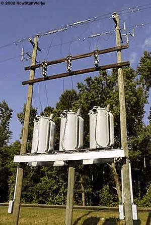
Are you some distance from the substation?
Are you on a rural power line?
do you see something like this between your plant and the substation?
image_doibsk.png


Bill
--------------------
"Why not the best?"
Jimmy Carter
 
Hi Bill,

Yes I am sure there are regulators and reactors between us an the substation. This is a rural town which is about an hour from the closest City. The distribution lines most likely travel far for servicing this area. There are some major industrial clients nearby (large copper mine), but they have their own transmission sub stations. That being said, we do notice that this gets better/worse throughout the year as more than likely the regulators are adjusting for line loading. That being said, the client is interested in getting to the bottom of this and a power meter isn't expensive to hook up. We know that everything runs fine on the generator, so something is more than likely wrong at the utility - but we will see.

I'll make sure to keep this thread updated with the results.
 
Hi triden.
How are you coping with the situation now?
Are you throttling the pump discharges to drop the current?
You are incurring losses.
The excess current is causing heat loss and reducing the life of your pump motors.
How much?
Do you log the volume of pumped water?
When you get the power analyzer, I suggest a test to determine how much the unbalance has cost you.
Run a pump on the analyzer and see the energy consumption per volume of water delivered. Do a reasonable range of pumping rates and log all data.
Run the same pump on the generator and repeat the test with the analyzer to determine the energy consumption per volume of water pumped efficiently.
Look at the volume of water pumped in a month and look at the corresponding power bill.
Calculate the cost of pumping that much water at the power consumption had it been on the generator.
Depending on the finding you may want to just get it fixed, or you may want to pursue a request for a rebate on the wasted power.


Bill
--------------------
"Why not the best?"
Jimmy Carter
 
Hello friend.
I'm waiting for the results of the power analysis.
Look for indications of unbalanced phase impedances.
ie: Not enough transpositions in the distribution circuit.
From what I have learned offline about the distances involved and the other loads, I have to consider unbalanced impedances as much or more than unbalanced loads.
One thing that I have not mentioned.
Be sure to get phasor diagrams of the incoming voltages with the pumps oflline.
Your pumps will be trying to correct any unbalances in the incoming power and you may see the worst case unbalances when the transformer bank is unloaded.

Bill
--------------------
"Why not the best?"
Jimmy Carter
 
I have seen quite a few regulators that only regulate on two phases and this really messes with the balance/imbalance. Does the problem vary with time of day and system load?

Mark Empson
Advanced Motor Control Ltd
 
I lost two transformers from extreme heat at a hotel complex. Miles away but on the same distribution there was a three regulator bank with one regulator out of service. The unbalance on the wye:delta bank at the hotel toasted two transformers.
I did the original installation as wye:wye. Some local expert changed it to wye:delta.
On a delta distribution circuit two regulators will work well, but not on a wye circuit.
Unbalanced loads may be troublesome with either system.

Bill
--------------------
"Why not the best?"
Jimmy Carter
 
Hello Triden;
Have you had any luck with the power analyzer?
Do you have access to any presently unused window CTs?
Yo may try using a window CT on one of the motor leads to even out the phase angles.
Actually you want to add inductive reactance to the best phase to bring it down in line with the more shifted phases.
Short the secondary.
You may pass the cable through the window more than once as long as you don't go over the CT rating and smoke the secondary.
This is for testing only.
I suggest trying this on one motor with the power analyzer connected.
For a permanent resolution it should be on the utility side of the meter to avoid PF penalties.
The inspiration for this is the old "Wireless Reactor".
This was a device used back in the 30s and 40s probably.
It was used to add impedance to a pole transformer to allow two transformers with different impedances to be connected in parallel.
It was a stack of laminations about 5" or 6" square and about 10" high. It was mounted beside the transformer and one of the secondary leads was passed through a hole in the lamination stack.
It should help to correct any problems cause by poor transpositions on your supply circuit.

Bill
--------------------
"Why not the best?"
Jimmy Carter
 
Status
Not open for further replies.

Part and Inventory Search

Sponsor