Eng-Tips is the largest engineering community on the Internet

Intelligent Work Forums for Engineering Professionals

Strange measurements in a 75/1 CT - 20/0.4 kV Transformer generating reactive power?? 1

Status
Not open for further replies.

Eduardo Diaz

Electrical
Oct 1, 2020
8
0
0
ES
Dear all,

I am new to the forum and I would like to say thanks in advance for wahtever insight you may give me about a recent issue I have found.

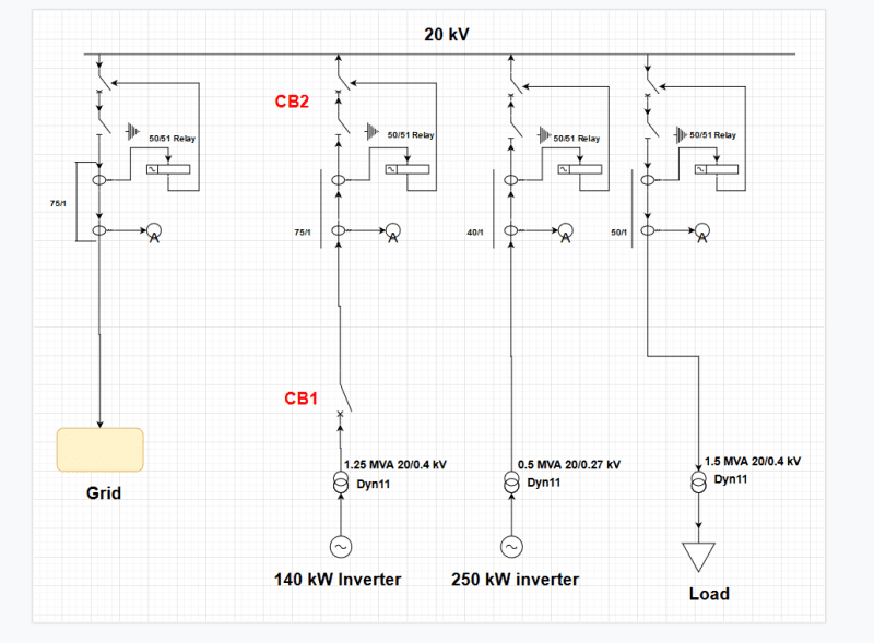
We have a 20 kV switchgear center and in one of the switchgears, which allow the injection of energy generated by an inverter, there are two 75/1 A current transformer (measurement and protection) (75 A nominal current at the primary), which are clearly oversized as the maximum apparent power flowing through that switchgear at 20 kV will be 200 kVA at most. The cables at the secondary of the CT are simply H07V-K non shielded, and all the switchgears are next to the other.

After the 75/1 CTs (there are one for measurement and another one for protection) there is a circuit breaker with a disconnector. Before the 75/1 CT there are only a 1.5 MVA 20/0.4 kV power transformer (also oversized), followed by a circuit breaker and a measurement equipment. So, summarisizing, after the inverter there is a 1.5 MVA power transformer, measurement equipment, circuit breaker (CB1), 10 m 20 kV cable, 75/1 A CTs, disconnector and circuit breaker (CB2), and the rest of the plant, in this order.
We have found 2 big issues that I would like to share with you in case you may give me a hint of what's going on.

1) When we disconnect the CB1 of the switchgear and the CB2(so there shouldn't be no power flow and current through the CT whatsoever), I am pretty sure of this), the CT still measures current. At 20 kV it is measuring 0.15 A approximately. The other switchgears are injecting current so there could be induced currents, but the 20 kV cables are shielded. If I have explained myself correctly, it should be understood that the circuit between the power transformer and the CB1 is completely isolated, and still measures current!

2) When closing both circuit breakers, with the PCS just consuming active power for their auxiliary services, the measurement equipment registers a 20 kVAr injection from the power transformer to the rest of the installation.

Looking forward for your replys.

Thank you very much!

Kind regards,

Eduardo
 
Replies continue below

Recommended for you

SLD_dhbe6g.png
 
My thoughts, ordered by the answer's usefulness:

2) 20 kVAr seems to be right for the magnetizing power required for the transformer (1.6 % of rated power). With the inverter just consuming for auxiliaries, the transformer is almost unloaded and, from the grid point of view, acts as a mostly inductive load.

1) No idea what's going on, really. But some inputs: Could the interference come from the CT secondary circuit instead? I'm not sure either how effective is the typical shield in MV cables against external electromagnetic fields.

Hope it helps.
 
Hi!

Thank you so much for you replies!

argotier: As far as the 20 kVAr is concerned, the problem is that it appears that the transformer is generating those 20 kVar, i.e., the measurement equipmente is displaying that the grid is absorbing 20 kVAr from the transformer. I have even thought about a insulation fault, and that there are parasite capacitance really high making this effect (but it had to be really high parasite capacitances...)

RRaghunath: The 20 kV cables include a shiled, so that would be a possibility. We have also seen that as there are greater current in the switchgear next to it, there are more current. These currents don't deliver neither P nor Q, but still there are.

stevenal: mmm... I will check it out and I will keep you informed guys

There is still a big question for me, how is it possible that the equipment is displaying a 20 kVAr injection from a transformer in no load operation...

Again, thank you so much everyone!

Looking forward to hearing from you.

Eduardo
 
Eduardo Diaz,
"how is it possible that the equipment is displaying a 20 kVAr injection from a transformer in no load operation." - Do you have long power cables that are also energised when transformer is energised (but not loaded)?
Capacitance of power cables could produce that VAR when energised.
 
Eduardo Diaz said:
As far as the 20 kVAr is concerned, the problem is that it appears that the transformer is generating those 20 kVar

Very strange, I cannot see anything in your circuit that could cause it.

The MV cable lenght (10 m) is too low to produce the 20 kVAr measured, I've made an aprox calculation and you would need a 2.5 km cable to produce that value (and I'm not even taking into account the inductance of the trx).

I would check first if the CT circuit is properly connected: could be a polarity inversion somewhere and you are getting capacitive measurements when should be inductive.

Other possibility, less likely but who knows: are you sure that this reactive power is coming from MV side of the transformer and the inverter is only consuming active power? Some inverters have the capacity of reactive compensation (consuming/producing VArs), be sure is not the inverter that is supplying the VArs for some reason.

If I may ask, how this problems originated? This is a new installation and these things were noted from start or its an existing circuit and the problems showed up at some point (probably when something was changed)?
 
Looks to me like a measurement problem:

either the CT's or PT's phasing is not right. Since nobody mentioned it, I suspect a voltage mismatch in wiring.
Do you have access to the current and voltage phasors (vector diagrams)?
 
I would emphasize stevenal's suggestion, check the CT secondary grounding and make sure the neutral point is grounded at one point only. I've seen this a number of times, especially in powerhouses where there are a lot of stray magnetics. Also note, the MV cable shielding is electrostatic shielding, it is not magnetic shielding.
 
Hi everyone,

I apologize for the delay but I have had a really busy week.

RRaghunath: As argotier is saying, the length of the cable needed so that they were responsible for the Q injected should be around 2.5 km, but there are no more than 10 meters so I am discarding that option.

argotier: I will check it anyways, but I think the cables are well connected. Even if the 20 kVAr were inductive, it is too high as the no-load losses are around 1.5 kW. On the other hand, I am pretty sure that the it must be up the inverter, because we did the tests with the inverter disconnected and the 20 kVAr were still there. As far as I know, the problem has always been there.

unclebob: Thanks for your comment! The more I analyze this issue, the more I believe it comes from the CTs. I checked the phase and magnitude errors from the test dataheets and they are within normal limits. But I will check the phasors so that I can see if there's something weird in the angles.

mls1: Thank you mls1! I have also done some research and it seems the origin of the problem must be here. I will have to check it in situ, but I am including a schematic with the connections of the CT. The PE connection is for the power supply cables.
CT_diagram_ku62k7.png
 
Eduardo Diaz,
From the CT secondary wiring scheme in your message, the CT star point earthing is not done in the panel where the measuring device is located. It seems to have been done near the CT. Is that right?
The correct practice is to earth the CT star point in the panel itself. Could you verify please!
 
Eduardo, remember that an unloaded transformer demands a no-load current for two reasons:

1 - To account for the iron losses: hysteresis and eddy (active component of no-load current, in phase with the applied voltage).
2 - To magnetize the core (magnetizing component of no-load current, lagging 90º the voltage).

Now, the magnetizing component of the no-load current is greater than the active component and it will demand a larger power than the no-load losses.

As I said before, 20 kVAr is not an unusual value for the magnetizing power for a 1250 kVA transformer (~1.6% of rated power, in the same order as a typical no-load current for a similar transformer).

The weird thing is that the measurement is seeing it as capacitive, instead of inductive as it should be. That's why I think the CT connection may be wrong (or the PT connection, as unclebob said).
 
RRaghunath: I will go to the installation in the next weeks so I will be able to check it myself.

argotier: Hi argotier, there is one thing that I did not say about the 1250 kVA transformer. The no-load current is I0=0.175%, so I think those values of 20 kVAr may be too high.
 
Hi everyone,

After being in the installation, I have seen several things I would like to share:

1) The +19 kVAr we were seeing in the 140 kW PCS inverter comes from a filter installed after the inverter, so we have solved that issue.

2) As for the circulating currents, we have seen the 20 kV cables go through a toroidal current transformer. These cables include the shield, and we have to confirm whether the shield is earthed at two points but it seems the most likely thing.

I will update to you as soon as I know more.

Thanks a lot to everyone!

Kind regards,

Eduardo
 
Hi everyone,

Recent and probably last update.

We were in the installation to do some tests in the 20 kV cable shields. It turned out that they were grounded at two positions:

1) In the Switchgear Centre, they were grounded.​

2) In the HV side of the 20 kV/X transformers, they were also grounded.​

We isolated the 20 kV circuit from the transformer to the Switchgear Centre, generated a high enough power flow in the switchgear cells next to them so to induce currents, and we verified that no currents were induced. So finally, we have discovered the issue.
We are now wondering what to do in order to avoid this issue in a safely manner, but at least it is identified the issue.

Thanks a lot!

Kind regards,

Eduardo
 
See RRaghunath's Oct 3 post. How are the CTs installed on the cables? To get full insulation and to exclude the shield current, generally the CTs surround the full cable; then the shield connection is routed back through the CT window before it's connected to ground.
 
Hi stevenal,

The 20 kV cables with the shield included are passing through the CT window, so that's the problem. I have seen that the IEEE suggest to route back the shield connection through the CT window. The only thing that just bothers me a little bit is the fact that the window is not very wide and the shield and the cable jacket would quite close.

Kind regards,

Eduardo
 
Status
Not open for further replies.
Back
Top