Continue to Site

Eng-Tips is the largest engineering community on the Internet

Intelligent Work Forums for Engineering Professionals

  • Congratulations waross on being selected by the Eng-Tips community for having the most helpful posts in the forums last week. Way to Go!

Strategy for multiple curves at corner 4

Status
Not open for further replies.

AleksanderK

Electrical
Aug 20, 2015
15
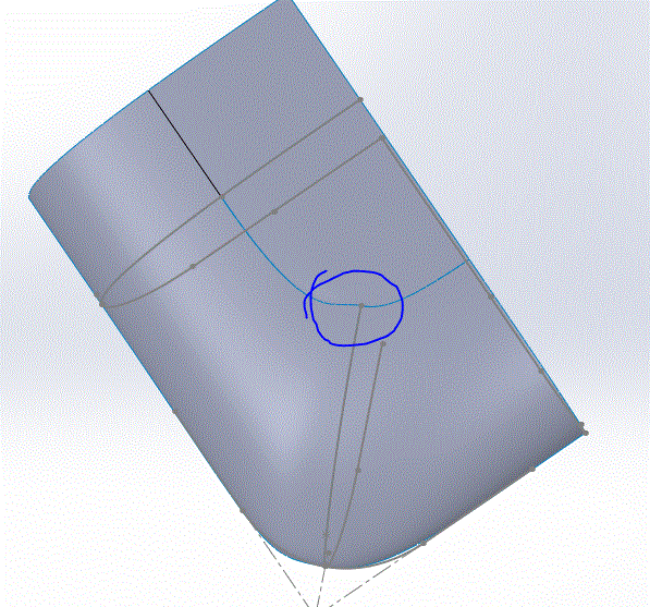
Can anyone suggest a strategy for getting good curvature bringing these curves together? Every time I add a hard constraint (such as a guide curve for a loft, or Direction 2 for a boundary), the surfaces become wrinkled.

The whole part is a just a rectilinear box with curved edges and a slightly curved top, and flat bottom, and this model is one corner of it.

The part will be injection molded.

I've put many hours into this, including training (instructor couldn't figure it out), tutorials, books, so I think I have to ask for help now.
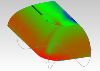
cornerproblem.poorsolution_ghzp7k.png


Replies continue below

Recommended for you

Start by cutting all the specified radii in half, and then again if necessary, until SW is able to produce a more cubist representation of what you want. Then increase the radii until it gets wonky, and then back them off a bit.


Mike Halloran
Pembroke Pines, FL, USA
 
@MH Thanks for thinking about this. That sounds like something very interesting, but I don't think I understand it. If all radii are at 50%, then the whole model is merely scaled, and so the SW internal algorithms won't be affected.

If you mean apply this rule only to particularly troublesome constraining curves, then I have gone much further than that: I've completely omitted them, for example the plan view curve on the split plane. This provides a very comprehensive improvement, but can only be implemented for the first surfaces you make (because later, something else will have to align with those unconstrained edges).
 
Where I'm going is that SW is basically just always trying to solve a set of equations, which you define indirectly, and that it is possible to define a set of equations that have no useful solution. That's where you are. So, yes, sharpen the weird edges, and/or change the way in which they are defined, and you have a chance of understanding exactly how SW is interpreting your desires differently from the way you think you have defined them.


Mike Halloran
Pembroke Pines, FL, USA
 
@MH Thanks for the clarification. That did finally dawn on me, and since then have been making many experiments, mostly splitting curves or removing constraints. Both work well, but only for the first set of surfaces, because after that, the first set become constraints for the subsequent surfaces, which then wrinkle. I just tried some radius manipulation; there are affects, but not improvements.

Perhaps somebody's seen this before and can be a more specific, or would like to have a try with the model (not that I want my work done for me, though).

Thanks very much for your thoughts, MH; it's reasssuring to know that I'm generally on the right track.
 
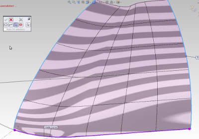
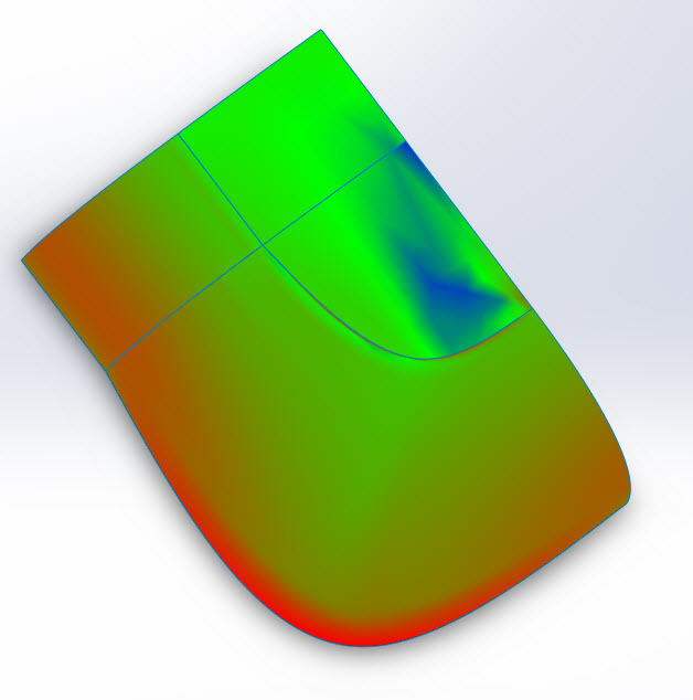
I must be missing something because it looks pretty good when I open it. The only thing I do see is something kind of wonky on what I will call the top surface at the radius 90° corner.
Capture_ky1xxq.gif
 
@djhurayt Thanks for looking at it. Yes, wonky. I betcha a bag of pretzels you can't get rid of it. Turn of curvature to see just how bad it is.
 
OK so that is the problem child area, let me take a deeper look-see
 
On "Surface-Loft1" and "Surface-Loft2": Try changing the Start/End Constraints (both Tangent Lengths) to .1
Or, change the Start Constraints to "None".

You are using SW 2014? I have 2015, so can't send it back to you.

Chris, CSWA
SolidWorks '15
SolidWorks Legion
 
Seems like you're working backwards, building corners first and then main faces. I'm sure there are more efficient ways to fail, but...
 
@ctopher Thanks very much, I see your point. However, I've used the tangent lengths to get the unconstrained edge at the split plane to align with the required shape shown in plane 'split' (instead of using it as a guide curve). If I change the tangents, then I will have to use the sketch as a guide, which will then drive wrinkles.

Another purpose of the tangent is to ensure that the flattening at the 45 plane pushes out toward the more rounded front and side planes. This flattening is very easy to achieve with a file and and epoxy cast, but is the source of the problem. I don't know how to get the flattening effect without pushing the tangents.

So I tried it anyway: tangents to 0.1, apply 'corner plan' sketch as a guide, and I get distortion caused by the change from line to pline in 'corner plan' sketch. Adjusting tangents does not yield an improvement.

tangents_o2ifmr.png
 
@TheTick: I have removed the other surfaces for clarity, leaving only their constraining edges. Yes, I have failed. That's why I'm here.
 
AK, can you confirm your version of SW, it looks like 2011. ???
 
@SBaugh Thanks very much for the attempt. The sketch 'corner plan' on plane 'split' is a constraint. The curves must not go outside this line, and this constraint drives some of the trouble at the top flattish area.

Also, there is supposed to be a flattish area at 45 degrees around the corner which seems to be not present in your screenshot, as depicted in sketch 'corner top.' Imagine taking a flat file to the corner (which is what I did) and largely flattening the corner, then blending it with the file into the other two edges, which rounded, not flattened.
 
Sorry. Maybe a bit harsh, but I want to drive home a fundamental flaw in your approach.

My point is that the corners should probably not be built independently. If the main faces and edges are used to drive the corners, it will require less definition and get a smoother result.
 
@TheTick I have found just the opposite: with fewer constraints, it is much easier to get wrinkle-free curved surfaces. Therefore, if you have a particularly difficult area, it may be worth creating it first.

However, this approach can only work for the first one or two surfaces (because subsequent surfaces will have to be constrained by preceding surfaces).
 
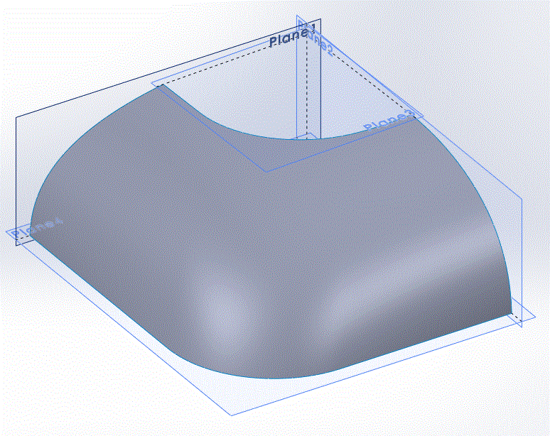
@djhurayt Looks good. How did you do it? I can open 2011 files, sorry, you're probably way ahead of that.
 
Status
Not open for further replies.

Part and Inventory Search

Sponsor