Continue to Site

Eng-Tips is the largest engineering community on the Internet

Intelligent Work Forums for Engineering Professionals

  • Congratulations SSS148 on being selected by the Eng-Tips community for having the most helpful posts in the forums last week. Way to Go!

Strawbale Construction: Roof-wall load transfer 1

Status
Not open for further replies.

Cam1985

Structural
Jun 5, 2020
4
Here in India experimenting with Straw Bale building.

There are two separate instructions from different expert sectors in the field of straw bale construction. Here are diagrams showing the differences:
SB-Timber_Fixed_Centrally_ak7fdv.jpg

IBC_Appendix_S_--_Top_of_Load_Bearing_Wall_o9oqmy.png


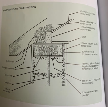
This building is challenging in that the plinth was built on top of a masonry tile floor, on top of compacted-earth, under the roof of a large and tall metal structure. I was involved after this plinth was all ready built, and walls were going up. The walls are built using the the load-bearing design method -- baseplate and roofplate/top plate compressing bales and reinforced with internal bamboo pinning.

Trying to design a roof that is lightweight enough to not overload the walls, but has enough weight to resist moderate wind speeds -- gusts likely no greater than 50-60 kmh, as this building is being built under the roof of another, larger structure, and is blocked from wind on two sides.

I would like to use a truss design that allows for switching out PUF panel insulation for bagged straw for testing purposes. I am thinking to have the trusses rest directly across the whole width of the top plate AND attach blocking on the inside and outside connecting plaster skin, roof system, top/roof plate.

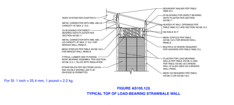
Does the blocking need to contact the whole length-wise face of the top of the plaster skin? I cannot tell from the IBC Appendix S image "Typical Top of Load-Bearing Strawbale Wall" if the 2x blocking that connects the roof, plaster skin, and top plate also contacts plaster surfaces across the whole interval between roof rafter/truss elements? Thoughts?

Here is a designs I've modeled, please share your thoughts:
Blocking_transferring_load_jfq0cl.png


Can the blocking be a 2"x6" board birdsmouthed/notched like shown here?

Appreciate insights -- thank you.
 
Replies continue below

Recommended for you

I have no experience in this so I won’t answer. I’m curious about how wind uplift and fire resistance are resolved however?
 
The first detail is similar to methods I've used for rubble wall construction, but without insulation. Potential problem is that the rafter load will tend to kick outwards. which needs to be resisted by a horizontal beam (tension member) tying both walls together. That is often provided at some interval, with iterlocking keys cut into the horizontal beam and the continuous runner on top of the wall. The continuous runner is somewhat embedded into the top of a rubble wall to distribute both vertical and horizontal loads. You need a way of allowing similar load transfer between runner and bales. If you use a truss to frame the roof, the truss' lower cord tension member would provide tension resistance to the kickout force and that lateral wall loading problem would be avoided entirely.

I don't see any sense in allowing any contact of the roof material with the exterior plaster skin, as shown in the second detail. Any load on the plaster skin there will surely tend to break the plaster outward and spall it off the wall. The blocking atop the plaster as shown in the third detail looks OK, as it to be of inconsequential load thereby not damaging to the plaster skin.

I am not understanding why there is an apparent void space just above the bales in the third detail. Something to try to evenly distribute vertical and potential lateral loadings there would be better than that void space between blocking members. Any lateral load there might simply overturn the void enclosure (blocking) members. Even with a truss, the void would seem to have no purpose.

The blocking only needs to be furnished with cutouts, if it is needed to flush evenly with the top of the roof rafters, or top chord of the truss. The third detail shows the blocking to be placed far too low for that purpose, so why do you need the cutouts?

“What I told you was true ... from a certain point of view.” - Obi-Wan Kenobi, "Return of the Jedi"
 
It is my understanding that the blocking does in fact sit on the "plaster for load-bearing walls" as in Table AS106.12 you get different bearing capacities depending on the plaster used. Additionally there are reductions if you use different types on each face. It doesn't appear in your model above that you have a lateral load path, take a look at the blocking and verify that you can drag the load from the diaphragm to the blocking to the built-up plate on the wall.

Also see section AS106.11:
AS106.11 Transfer of loads to and from plaster skins.
Where plastered strawbale walls are used to support superimposed vertical loads, such loads shall be transferred to the plaster skins by continuous direct bearing in accordance with Figure AS105.1(3) or by an approved engineered design. Where plastered strawbale walls are used to resist in-plane lateral loads, such loads shall be transferred to the reinforcing mesh from the structural member or assembly above in accordance with Figure AS105.1(3) or AS105.1(4) and to the sill plate in accordance with Figure AS105.1(1) or AS105.1(2) and with Table AS106.13(1).

@MIStructE_IRE - see AS107 in Appendix S of the 2018 IRC for fire resistance requirements.
 
If the plaster was supposed to be a structural element, you'd think that the minimum strength and thickness would at least be specified. It's really only there just to keep the straw dry and maybe the rats out.

Cam1985 are you going to use that AS plaster specification in India, or are you going to use "run of the luck" plaster at an unspecified thickness?


“What I told you was true ... from a certain point of view.” - Obi-Wan Kenobi, "Return of the Jedi"
 
The minimum strength, thickness, type and reinforcing are specified in the tables in Appendix S of the IRC.
 
Thank you all for your responses. Will respond to specific items here:

Reponse to [@ax1e] "I don't see any sense in allowing any contact of the roof material with the exterior plaster skin"
It is counterintuitive, but there's been lab verification done of the strength the plaster skins add, once cured. Appendix S design specs call for a mesh to connect the foundation, wall, and roof systems, and for that to be plastered on top of. I understand your point though -- I didn't believe it until I spoke with a structural engineer in Berkeley who showed me why this is the case. The plaster makes contact with the top of the foundation/plinth, and in the figure AS105.1(3) it shows blocking connecting the plaster skin, roof elements, and top plate.

"I am not understanding why there is an apparent void space just above the bales in the third detail." That is just the 3D model. The top plate is framed with 100mm x 50mm timbers and cripples at regular interval spacing. The void is filled with packed chopped straw for insulation (see images below)

This is the top plate, pins installed into top layer of bales (bales are internally pinned with 1.2 meter x 3 cm diameter bamboo pins at 4th & 6th elevation layer)
Roof_plate_w_pins_fozois.jpg


This is chopped straw packed into the top plate.
Roof_plate_straw_infill_bjpq1o.jpg


Top plate closed and sealed
Roof_plate_w_plywood_top_k4mn5c.jpg
 
Further replies:
Plaster thickness will be approx 1.5 inch. There will be three interlocking layers:

Clay slip to prime the bale walls to hold the intermediate layer
Intermediate layer composition will be determined by multiple sample trials done with varying ratio mixtures of clay, sand, straw, cow dung, and lime (there will be ratios that include zero values for each of these).
Finish layer of lime (we've had calcium oxide slaking for 9+ months now).
 
@Aesur "It is my understanding that the blocking does in fact sit on the "plaster for load-bearing walls" as in Table AS106.12 you get different bearing capacities depending on the plaster used. Additionally there are reductions if you use different types on each face. It doesn't appear in your model above that you have a lateral load path, take a look at the blocking and verify that you can drag the load from the diaphragm to the blocking to the built-up plate on the wall."

Yes, it is the case, according to Appendix S, that blocking does sit on the plaster. The plaster is applied after the roof is put on, with the elements the plaster will be applied to be in contact with.

As for lateral load path, this response applies to [ax1e]'s "run of the luck" comment regarding India -- this building was under construction when I got involved in the project. A brick & mortar plinth, concrete plastered, had been constructed, as well as a wooden base plate. There wasn't even a completed design before this took place, just some sketches by a colleague I work with here who is from another country in Africa where there is also a lot vernacular architecture. Problem is, the dimensions of the building have long enough spans to make the roof design less than simple, and the load calculations and designs difficult.

To be clear, this building is for vegetable cold storage, and only meant to test that thermal properties of straw bale construction. We have help from some architects and structural engineers familiar with this construction method helping with future structures, but I am on my own to complete this one that I didn't start. It is really pretty frustrating at times. I am trying to get a roof on the thing before the monsoon comes, and trying to do my best with truss design and the wall-roof connection assembly.

Any pointers you have on these elements is greatly appreciated.
 
Status
Not open for further replies.

Part and Inventory Search

Sponsor