Continue to Site

Eng-Tips is the largest engineering community on the Internet

Intelligent Work Forums for Engineering Professionals

  • Congratulations SDETERS on being selected by the Eng-Tips community for having the most helpful posts in the forums last week. Way to Go!

Strengthening a Soviet era 12 m RC beam 1

Status
Not open for further replies.

nivoo_boss

Structural
Jul 15, 2021
132
Hey everyone!

I have a situation where a Soviet era RC beam (it's sort of like a truss, where the chords are wider than the middle part of the beam) has its bottom chord cut with most of the rebar and cables cut - seems it was done a while ago to fit a goddamn door, thank god it has stood this far.

Anyway, something has to be done about it. I have pictures below to explain the situation better.

1)This is the current situation:
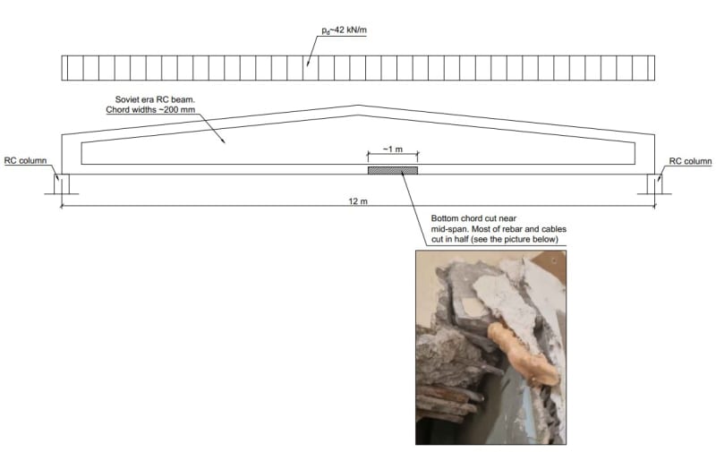
01_RC-beam-current_nhk5aw.jpg


2) And this is what I'm thinking about proposing to the builder. What do you think?
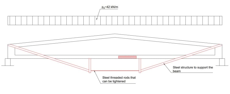
02_RC-beam-strengthened_hxaxnk.jpg


I got this idea from a local book written by a renowned civil engineer. The book is about structural failures and this was used to support an under-designed rectangular RC beam.

Perhaps some of you guys has some experience with something like this as well? Any help is appreciated.
 
Replies continue below

Recommended for you

nivoo boss said:
...its bottom chord cut with most of the rebar and cables cut...

1. "Cables cut" indicates that the existing beam may be prestressed concrete, not just reinforced concrete. Probably pre-tensioned, as in precast pre-tensioned concrete.

2. Your proposed fix/repair/strengthening is a somewhat common technique called external post-tensioning. Most typically using multiple 7-wire strand tendons, often in a harped configuration, and anchorages at the ends at approximately mid-depth of the section, with stressing at one end, assuming access is available.

Check out this document for additional information on external PT: Link

 
I'm not really following the diagram. It really needs a cross section through it to see what is going on here. Is the middle space open or is it a web?

What's with the [plan view and what does 42kN/m have to do with anything?

Is this "beam" really as shown? with no intermediate struts?

Where the load coming from?

What does the X section of that bottom beam look like? - width , depth and amount cut out.

how many cables? and re bar left? I would assume this beam is in tension other than self weight bending?

Can you not simply bridge across the gap using either metal plates or cables?

Are there cracks anywhere in the existing beam or evidence of movement?

The Russians tended to go big and strong without a lot of thought sometimes.


Remember - More details = better answers
Also: If you get a response it's polite to respond to it.
 
The beams look like this - a few pictures below. But anyway, since I was on vacation and the builder was in a hurry of course, another designer took the job. He hanged a HEB400 steel beam under the RC beam, so that when the RC beam deforms, the HEB will take the load and transfer the forces to the columns.

01_ilwt4i.jpg


02_cgzkr6.jpg
 
But is it really vertical load in that lower member or axial tension??

But if the new beam is good to take the load then ok, one way to do it.

Remember - More details = better answers
Also: If you get a response it's polite to respond to it.
 
Status
Not open for further replies.

Part and Inventory Search

Sponsor