Continue to Site

Eng-Tips is the largest engineering community on the Internet

Intelligent Work Forums for Engineering Professionals

  • Congratulations KootK on being selected by the Eng-Tips community for having the most helpful posts in the forums last week. Way to Go!

Strengthening concrete beam with steel channels 3

Status
Not open for further replies.

KutEng

Structural
May 27, 2019
40
I have an existing concrete beam that is already showing excessive deflections under just dead load conditions. The beam will be loaded up with additional dead loads and we are required to strengthen the beam to a) prevent further deflections (and reduce deflection if possible but I believe the deflection is due to creep and can't be undone?) b)increase the strength of beam to take extra loads

I am a bit out of my comfort zone here as I don't have much experience with strengthening existing structures. I have suggested using FRP strips however the headroom is apparently already too tight below the beam and they can't afford to go any lower. We are now looking at fixing a steel channel or 2 to either side of the concrete beam to strengthen it however I am unsure how to design this. In other posts, I have seen terms like strain compatibility and shear flow which I think I understand as a concept but I'm unsure how to actually check this.

Would external post-tensioning be ruled out if I can't go below the slab?

Thanks in advance
 
Replies continue below

Recommended for you

My gut feeling is that your shear flow demand from the concrete beam to steel channels will be extremely large. I think you will end up needing a tremendous amount of fasteners that will make this more or less cost ineffective. I have never strengthened concrete with surface applied steel before, though, as corrosion would be the Achilles heal in my industry.

What are the dimensions of the beam? Span length? Do you know the existing reinforcing configuration.

You mentioned excessive deflections under just dead load. If you have as-builts and they show that the beam was not grossly under-designed, then I too would assume that they removed the shoring too early during construction and now you have irreversible deflection. Either that or their formwork/falsework sagged during the concrete pour.

You mentioned FRP strips. 95% of applications I would recommend wet layup FRP. You saturate the dry FRP with epoxy and apply it to the soffit of the beam. One of the benefits of FRP is that it doesn't utilize any headroom. Each composite ply of FRP is 0.04 inches thick. So as long as the applicator has room to install the system, I'm not sure why you say this wouldn't work cause of headroom. I would recommend carbon fiber since it has a higher modulus, typically around 14,000 ksi. Not as high as steel but considerably higher than concrete. This will increase your effective section properties of the beam.

You will want to refer to ACI 440.2R. I like to do FRP designs myself, however, I know plenty of Structural Engineers who think it is beneath them or don't want to be bothered learning something new so they punt to the FRP manufacturer and have them design the system for them. If you are struggling with terms such as strain-compatibility and shear flow, you might want to have someone else do the design as these are pretty basic engineering terms and strain-compatibility is everything to externally applied FRP theory.

If you do decide to go with FRP, and your concrete is deflecting for reasons other than I previously mentioned, you will probably have lots of cracks. Those cracks will ALL need to be pressure injected with epoxy prior to applying the FRP system. Don't skip this step!

You could go with external post-tensioning, however I would think that if you are feeling out of your comfort zone with the strengthening using channels and FRP, that post tensioning would be even more daunting as it is an order of magnitude more difficult to get right. Think about how you would do your anchorage at the jacking points....
 
Design side channels (if you can't get them - make them) and forget about any strength from the existing concrete. Once put a double truss on each side of a concrete beam (about 6 feet deep)in place. Created holes in the concrete to transfer the beam weight to the truss (including a lamalla roof). Concrete beam was shored until the truss was in place. I think the span was about 50 to 60 feet. The original building had been constructed in the 1930's. (Purity Grocery Store for those who can remember that far back). Assembly went through Loma Prieta a little later.
 
STrctPono said:
What are the dimensions of the beam? Span length? Do you know the existing reinforcing configuration.

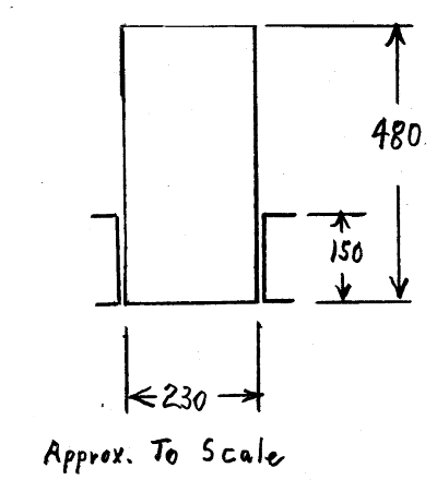
The beam is 480mm deep x 230 wide, spanning 6m and has 3 N16 twisted bars bottom(scanned) and we assumed 3N12s top. The beam does seem to be under reinforced and has 5-10mm flexural cracks every 200mm. There are signs of concrete cancer in areas around the beam and evidence of what appears to be repairs to corroded reo.

STrctPono said:
One of the benefits of FRP is that it doesn't utilize any headroom. Each composite ply of FRP is 0.04 inches thick.

Most would believe this to be the case however we presented this to the owner who parks their car beneath this beam and they were not willing to lose any headroom at all (I don't think they realise how expensive their peace of mind is going to be). So, unfortunately, FRP is still out of the equation.


oldrunner said:
Design side channels (if you can't get them - make them) and forget about any strength from the existing concrete

This was my initial plan and would be ideal, however, I'm limited to a depth of 150mm for my channels and I'll need to consider the strength of the existing beam to get the capacity out.
 
Have you checked the current capacity? With 5-10mm cracks every 200mm, it would appear that the bottom steel is grossly under that required and the reinforcement is well past yield even at service loads.

FRP will not reduce the deflections and would also need to be fire protected.

External prestressing could be added on the sides. But it would have to be enclosed eventually for fire rating. This could both improve your deflections and give you the strength you need, depending on how bad the existing concrete is. You would have to attach angle change saddles and anchorage points pn the sides of the beam.

Ingenuity is into this sort of repair but I am not sure if he is still operating in Australia. Hopefully he will reply.
 
Rapt,

That is correct, the beam does appear to be under reinforced - if the steel has yielded does that mean if I go with the steel channels I can't consider the beam as contributing to the strength?
 
If your channels cannot be deep enough, consider tubes - narrow or wide - even if they have to be fabricated. I would also consider telling your client to shore the beams now. That might get his attention! How old if this building? Twisted rebar is some sort of a clue. Are you going to jack the beam up to it's original condition?
 
The building was constructed in the 70's I believe - First time I've worked with twisted bars
I don't think shoring will be necessary at this point. The builder has removed the tiling and sand bed sitting on the slab coming into the beam so the beam is essentially unloaded now.

I am considering jacking the beam up but I don't think this will help as I stated above it seems the excessive deflections are due to long term creep
 
Ar Engineer,

I was design in the 70's and have never seen twisted bar!

Agree with oldrunner, the beam should be propped.

If the bars are well past yield at service, I do not think creep is the worst of your problems for deflection.

To take out the existing deflection, you are going to have to jack it up. But that does not help reinforcement that has gone that far past yield.

From everything you have described, if it was my beam, I would be replacing it!

 
Oh come on, rapt. Your memory is failing. We used C bars (which stands for cold worked by twisting) in Australia in the 1980's. I first started working here in 1983, and thought them a very strange thing at the time.

410C bars were replaced by 410Y (Tempcore) bars in 1983, but the twisted bars were still in use for a while after that.
 
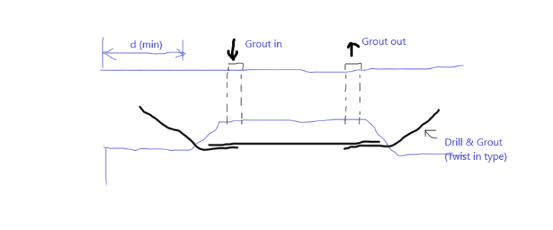
If it's deflected, then jack it up to give it a bit of camber. Drill it, through bolt it; you can use oversized holes through the concrete and steel. Grout the hole solid and weld plate washers to the channels ea side, with no tolerance. Release the jacks... done like a Thanksgiving turkey...

Dik
 
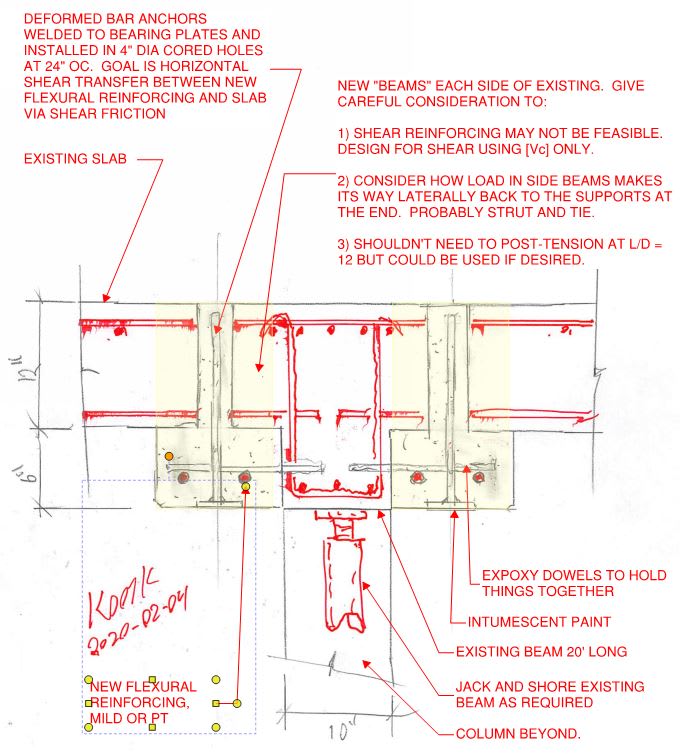
An idea, not ideal, but might work. Note the existing beam ends and adjacent slab panels are all to be shored.

beam_c28tle.png
 
Ar Engineer:
Take a look at the CZ13 steel sections. Probably not an off the shelf steel section for you, at most steel supply houses. They are a special steel section for railcar building and are shaped like a “Z”, so that their wide, thinner flange could fit below the bot. of the conc. beam, and their other, narrower but thicker flange would project outwards from the conc. about 13” above the bot. of the conc. beam. Or, as Oldrunner suggested (4FEB, 00:56) have your own custom shape fabed. to fit your conc. beam. That would be a full width bot. flg., a web on each side, and two outstanding top flgs., to carry the full load. Put the stl. beam around the conc. beam, jack both up so you have some predetermined camber; drill the conc. for through bolts, using pre-punched holes in the stl. webs; grout btwn. the old conc. beam and new stl. beam and release the jacks.

Your client will have to live with a little less head room, .5-.75”. Alternatively, he can just wait until the conc. beam rests on top of his cars, and then he won’t need all your expensive efforts. The cars can carry the load.
 
What about external post tensioning? might be much easier to maintain depth. Could put a cable on each side of the existing beam.
 
Ar Engineer said:
I'm limited to a depth of 150mm for my channels...
...if I go with the steel channels...

I have not done any calcs, but sometimes a simple, reasonably accurate sketch can say a lot:

IMHO you can take the added 150mm steel channel option off the table and look into other proposals being discussed.

Composite_Beam-400_tnzuls.png


1) The reduce deflection, moment of inertia has to be increased.

2) Consider the pair of 150 mm channels to be "perfectly" attached to the concrete beam.

3) Do the calcs (similar to flitch plate math) to determine the moment of inertia of the composite.

4) I think you will find that even with "perfect" attachment, 150 mm channels are not adequate to significantly reduce deflection.

[idea]
 
13" slab, not unusual. But compared to the depth of the beam, yes, it is odd.
 
Hokie66,

That is not what I was thinking of as twisted bar. Early (well before my time) reinforcing bars were square, and to help develop bond, they twisted them to give a sort of deformed shape.
 
So just found out the beam is actually 450mm deep - we found an additional 30mm of granosite on top when we pulled up the tiles
Slab coming into the beam is 170mm + there are services running along the top 130mm which cant be touched (read: can if we ask enough)

Kootk, adding your signature to drawings now I see... If things go south with this you can expect a court order at your doorstep [lol]
In all seriousness, I like the idea but I don't think it's very feasible at the moment - I'll leave it as a last option for now

Rapt & Hokie,
Square twisted bars are what i'm working with here... Just did a quick search and looks like they were around in the 50's-60's [upsidedown]

 
Status
Not open for further replies.

Part and Inventory Search

Sponsor