Continue to Site

Eng-Tips is the largest engineering community on the Internet

Intelligent Work Forums for Engineering Professionals

  • Congratulations Toost on being selected by the Eng-Tips community for having the most helpful posts in the forums last week. Way to Go!

Strengthening existing RC slab 2

Status
Not open for further replies.

mar2805

Structural
Dec 21, 2008
372
Hi guys!
I need some advice.
Please see picture atttached.

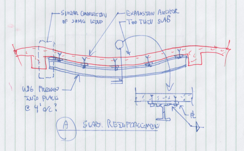
As you can see its an existing RC slab spaning in one direction.
Slab is supported by masonry bearing walls
The thickness is UNBELIVABLE for the given span. Only 5 inches!

The slab is said to me reinforced in bottom and top layer allthou I have my doubts in how the hell did they manage to put 2 layers of reinforcement in such a thin slab.
Ive done some calculations by hand and using FEM software and the reason for that large crack in the top layer of the support is clear.
There isnt enough reinforcement in the slab to satisfy the bending moment in the slab.
The problem now is that both, the bottom layer and the top layer were reinforced using the same area (said by the constructor).

Since thers a crack formed in top of the slab, the negative bending moment will tend to go to zero value and in return the positive bending moment in the bottom of the slab will increase (since this will become a simply supported slab system).
I calculated that the reinforcement in the bottom of the slab isnt capable of resisting "increased" positive bending moment, BUT the slabs hasnt started cracking yet on the bottom side.
These are good news.

I need to strenghten the slab.

My idea was to cast RC beam under the slab.
There would need to be 3 beams for each field spaning in the short direction.
This would be done by making formwork for beams under the slab and by pouring concrete thru holes that would be made in the RC slab.
Theres 3 beams would lower the bending moments in the slab to an value that is small enough for the reinforcement to resist it.
We have done some FEM modeling and analysis modeling the new RC beams that are not "monolitical tied" with the slab.

The numbers seem fine but there a lot of questions that are bothering me...

Has anyone done such a thing already?

Thank you
 
 http://files.engineering.com/getfile.aspx?folder=a95fea1d-5ddc-430a-88fd-dcf895cab03e&file=RCslab.jpg
Replies continue below

Recommended for you

I too was thinking of a wide flange beam. I'm not a fan of the proposal by mar2805 (OP).

Yes, a shallow saw cut filled with flexible sealant would be a neat way to hide an unsightly crack. Whether or not it is worth the trouble depends on the finish to be applied.

BA
 
Is this what you have in mind?
See picture attached.

Few problems.
How would you solve the lost of contact between the beam and the slab due to slabs curvature?
There will be around 1/2 to 3/4 inch gap between them.
I doubt using steel wedges will be sucesfull.
Would you only fix the beam at the supports with no direct connection with the slab?

@KookT
I have around 7 inches free space under the slab.

 
 http://files.engineering.com/getfile.aspx?folder=cdf105fc-1f4a-42fc-b0a7-94397dbec4f3&file=ibee-page-001.jpg
You could jack the slab upwards, install the beams and pack, release the jacks, slab will bear on the beams.

Alternatively fit some flat jacks between the beam and the underside of the slab. Both options will have the benefit of attracting both the self weight and the imposed live load from the slab.

Another option is to use an expanding cement to fill the gap between the beam and the slab, poured through a hole in the slab.

 
That is what I had in mind. Dealing with the gap is easy, My detail resolves that with some adjustable bearing plates. The more pressing question, I think, is whether or not a 6", non-composite beam can successfully be designed for strength and deflection. If not, an underside strapping solution might be required. Or a composite beam.

I like to debate structural engineering theory -- a lot. If I challenge you on something, know that I'm doing so because I respect your opinion enough to either change it or adopt it.
 
See below for a potential strengthening strategy.

- beams added at regular intervals as reinforcing rather than isolated girder support.

- you probably get pretty good composite behavior but, for starters, maybe see if you can make it work by the numbers non-composite.

- start the fastening from the middle and and use the steel beams to straighten out the concrete to some extent. Might be cheaper than shoring and jacking.

Capture_02_hxfwbh.png


I like to debate structural engineering theory -- a lot. If I challenge you on something, know that I'm doing so because I respect your opinion enough to either change it or adopt it.
 
@KootK

So your idea is to use closely spaced steel profiles that would act as "reinforcing".
Basicly they would increase the moment resistance of the slab in one-way spannig direction.
Slab would still behave as one way spaning.

This is contatry of using 2 large steel beams, each positioned at 1/3 of the longer direction of the slab.
Seem my first post and posted sketch - 33 feet divided into 3 bays, each 11 feet wide to 13 feet long, wich would try to make slab span in two direction IF the steel beams are stiff enough.
 
If the steel beams can bear on the masonry walls, that is the way to go.

BA
 
@KootK
You havent answered my previous question

"So your idea is to use closely spaced steel profiles that would act as "reinforcing""
 
Sorry mar2805, I hadn't realized that there was still a question left outstanding. Yes, your interpretation of my suggested solution is accurate.

I like to debate structural engineering theory -- a lot. If I challenge you on something, know that I'm doing so because I respect your opinion enough to either change it or adopt it.
 
Kootk thanks for the response, but I cannot agree with you on you last statement of this being an "reinforcing option" for the slab in one way direction.
I think that only epoxy glued steel plates and carbon fibre strips can be defined as reinforcing solutions that would increase slabs carring moment in the bearing direction.
These are all objects that "dont have" any Area moment of Inertia as they are not solid members resisting bending.
On the other hand, if you put an steel beam under the slab that has significant stifness and its area moment of Inertia, the slab will try "resting" on the beams and will probably in return have an effect of span shortening or reversing slabs direction.
 
Hello guys,
I hope i'm not too late... it's an interesting subject.
So, from what i read here @mar2805 you are trying to prevent the failure of that poor reinforced slab. I think that serviceability and crack limitation are out of topic.
The failure can occur by:
- reaching the rotation capacity of the top section (rebar break)
- yielding the bottom reinforcement and creating a second yield hinge that will tranform the slab into a mechanism with 1 degree of freedom - large deformation and failure by reaching rotation capacity
(i can make sketchs if needit)

So the straightforward solution is to increase the bending moment capacity on the top or on the bottom. Increasing top capacity is hard on this stage so i will discuss the second solution : increasing the bottom bending capacity at the middle of the 2 spans.
It may appear as a simple topic but the calculations needit to be done for an exact solution can be quit hard and time demanding.
First you have to evaluate the bending yield capacity of the top section where the cracks are produced. I would suggest to go with the values of steel and concrete strength specified in the rehabilitation codes (consolidation codes) because they use the average (a lot more realistic) values not the probabilistic ones used in new designs, it's a big difference, about 20-30%.
After that you need to evaluate the rotation capacity of that section - same from consolidation codes - and check how much you have remain until is very bad; how do you do that? Measure the bottom deflection in the reality (in site) and calculate the theta (rational angle on the top) that correspond to that deformation (use any structural analysis software). Now you can have some ideea of how big is the danger of failure.
Every new added load on the slab will : 1. increase the rotation angle at the top and 2. increase de bending moment at the bottom (this is redistributed from the top because the yield hinge that is already at full capacity).
In this point with the maximum probable loadings and moment redistribution from hinge the bottom section will remain in elastic domain or will produce another yield hinge? If yes than you have a failure mode by losing the only remained restrained degree of freedom you have.
To avoid this you have to increase bottom slab capacity so that with the maximum loads will not yield (or yield with very small rotation - very little).
Increasing the bending capacity can be made in various ways but i think that KootK's solution with some modification is the optimum cost efficiency.
Creating a composite section is the best but is not so simple to check in design stage. The key in the making the steel profile and concrete slab to work togheter as a composite element is the shear connectors. If they dont hold than you dont have the extra bending capacity from the new steel. So first you have to choose a target capacity of the bottom composite section, as i said, you can choose the maximum bending moment from redistribution with the max loads but you have to check too if the deflection is not above the limit that produce steel failure from rotation capacity on the top section !
I would go with steel channels with mid holes for the shear connectors from steel reinforment - minimum 16mm diameter- fixed with chemical anchors to the slab. The span between the shear connectors and the number of them need it result form composite bending capacity calculation - just like composite deck on steel structures. The span between channels result from steel required to produce that bending moment - you can set the span to be 1 m and choose the profile dimensions from thet bending necessary.
So you can see that selecting a optimum solution can be quit tricky...


Status
Not open for further replies.

Part and Inventory Search

Sponsor