Continue to Site

Eng-Tips is the largest engineering community on the Internet

Intelligent Work Forums for Engineering Professionals

  • Congratulations KootK on being selected by the Eng-Tips community for having the most helpful posts in the forums last week. Way to Go!

Stress analysis of a thin laminated plate subjected to a transverse load / bending.

Status
Not open for further replies.

fernandosalvador

Mechanical
Jul 13, 2015
2
Good evening friends,

Suppose I have a square plate (2" x 2"), of a carbon/epoxy laminate, for instance with 4 layers: [0,+45]s, where one edge is fixed, and in the opposite edge, a transverse load (say, in the Z direction) of 1000 lb is applied, producing a bending. (pretty much like a cantilever beam, I guess)

|
|
_________ v
/| |
/| |
/|_________|


I'm trying to figure our how can I perform a analytical stress analysis of the laminate with these boundary conditions neglecting moisture and thermal effects.
I tried to use the CLT with a moment Mx of 500 lb/in/in but seems that this approach is wrong, since the transverse load of 1000 lb will induce a non-uniform moment, and also a shear stress (?), which I don't know how to represent in the calculations.

In order to be clear, my first main goal here is to determine the strains and stresses along each ply (top/bottom). And plot a graph of the stresses trough the thickness.
Is the Classical Laminate Theory enough to predict those results?

I have those books that might help:
"An introduction to composite materials" - Hull (1st ed)
"Introduction to composite materials design" - Barbero (1st ed)

However I'm still in the beginning of the course here in US, I have 20 years old, and English is my second language, so I'm still struggling to find this answer on those books.

I really appreciate your attention, and I'm looking forward to get some answers to extend my knowledge and hopefully be able to improve my community. Thanks.
Fernando.


 
Replies continue below

Recommended for you

Your illustration fell into the multiple spaces being replaced by one space problem. However it's pretty clear anyway. The moment/width as described is 1000*2/2 = 1000 lb-in/in (note units for a running moment).

First analysis would be as you have suggested, surface stress = load at free edge times length / t^2 / w / 6. This is non-conservative and a CLT program will be a bit more accurate, as the 45s in the middle will not contribute much to resisting the bending moment. Missing out the 45s is one option to do a hand calc which is probably conservative (for (0/45)s stress = M*t/2/I, I = 2*tp^3/12 + 2*tp*tp^2, tp is ply thickness (assuming tp 0° = tp 45°), but see below to address the lack of uniformity across the beam's width). You can of course do a CLT analysis by hand if you've got the patience.

The non-uniformity of the load across the width of the beam can be addressed by hand with something like Roark (7.12 in Ed. 6, beams with Wide Flanges; Shear Lag). This is based on work by Jaramillo and assumes a point load at the edge of the flange. As such it will be conservative for the distributed load that you seem to have (or be assuming...).

Generally this will be good enough for a preliminary RF/M.S. The shear will reduce the value a bit but not by much. You could try using something like Tsai-Wu with the through-thickness shear applied as in-plane shear, but it's not really worth it. (Depends on what other simplifications/approximations you're making.)

An actual shear failure is likely to be when the interlaminar shear strength is exceeded, so P/(4*tp*w), 1000/(4*0.01*2) = 12500 psi (assumes woven material about 250 gsm or maybe 0.8 oz/ft^2); a likely ILSS is 8 or 10000 psi so 1000# and 2" wide by 0.04" thick actually looks slightly dubious just from the shear point of view.

Mind you, we've got massive in-plane stress with 1000 lb and just 2" wide x 0.04" thick. As your sketch implies much more than 4 0.01" plies needed to avoid failure of even the best carbon.

The sorts of simple conservative methods I've described work in reverse to arrive at a conservative thickness. You should be seeing an allowable stress for a 0/45 woven carbon of about 25, maybe 30 ksi. That implies quite a thick plate which will in turn make the ILSS problem go away.

The modern approach would be to use a simple FE model, but for a situation like this the hand methods give the most flexibility. Move to FE when the problem is a bit better defined with more complicated geometry and loading.
 
Oops. "First analysis would be as you have suggested, surface stress = load at free edge times length / t^2 / w / 6"
That should of course be "First analysis would be as you have suggested, surface stress = load at free edge times length * 6 / t^2 / w." Only a factor of 36 out in a nonconservative direction...
 
RPstress,

I'm grateful for your answer and effort to explain these details for me.

As you suggested, I changed the moment from 1000 lb-in/in to 5 lb-in/in (and corrected the units)

I also looked further to perform an FE analysis on Solidworks composite feature.
I used the same 2" x 2" model [0/45]s with the same boundary conditions defined previously. (I used a force of 10in-lb/in since is 2" long and wide)

For the first ply (top) stresses I found these results:
Untitled_ual512.jpg


But now, what I wanted to do is to predict these results analytically.
I completely understood what you have said about the shear stress consideration, I also checked the Roark theory, which I believe won't fit this load case. Neglecting the 45 plies can of course be a conservative approach but I wanted to be as precise as I can get. So I guess the CLT is the right track on this.

So I did analytically starting with same values for E1, E2, G12, V12 and V21 that I used on FE, with ply thickness of 0.005 in
I calculated by hand:
-Q matrix
-Q bar matrix
-A matrix
-D matrix

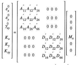
Then I putted together the ABD matrix with a Moment Mx of 5 in-lb/in like this:
2_fv7hl5.jpg


After computing the deflections (K's), I was able to compute the midplane strains and then the stresses acting on each lamina
For the top of the first ply, the same showed on the FE analysis above, I got the analytical result of 83,500 psi, which seems to match at some level the software result (about 2% diff)
However, all the results for the other plies, and also the Tau stresses are not matching, what lead me to think that something is missing on my hand calculations.

I could perform the same case, but with an axial load (which in the CLT I represented as a simple Nx), and the results completely matched. But for the transverse load seems that something is wrong and I can't figure out how can I do the analytical calc.

What I still want to ask is:

- This is the right approach to complete the CLT analytical method?

- Since the transverse load acting on the edge induces a non-uniform moment (which varies along the length), is it right to represent it on CLT as a simple Mx moment?

Again, thank you very much for your time and patience,
Fernando.
 
If you're doing FE then there's no need for rough approximations with Roark (that was just a suggestion of a way to do a hand calc to assess the distribution across the plate).

Your surface ply doesn't match quite as well as you think. The CLT makes no estimate of distribution across the plate. It assumes an infinite plate. The stress it predicts should be about the average of the FE across the plate, which at a guess is about 70 ksi.

As for why the 45° plies are very different from the FE I can't say. Is the FE using layered elements? If so then most FE solvers take the basic material properties, preprocess with CLT to give anisotropic plate properties, analyse that anisotropic plate, and then postprocess with CLT to recover the layer stresses.

The implication is that the FE and the hand analysis are analyzing different things, probably an error in specifying the FE.

Most solvers will recover through-thickness interlaminar shear stresses, but they can't use CLT to do so. They do an analysis based on S*A*ybar/I engineering shear distribution. You will need to do an auxiliary through-thickness shear analysis based on the same. CLT does not address through-thickness stresses at all. For the same reason a curved laminate loaded by a moment will have through-thickness stress which can't be assessed by linear FE or CLT.
 
Status
Not open for further replies.

Part and Inventory Search

Sponsor