Continue to Site

Eng-Tips is the largest engineering community on the Internet

Intelligent Work Forums for Engineering Professionals

  • Congratulations IDS on being selected by the Eng-Tips community for having the most helpful posts in the forums last week. Way to Go!

Stress at Displacement Boundary Condition

Status
Not open for further replies.

Lee.Conti

Automotive
Nov 8, 2019
87
Hi all,

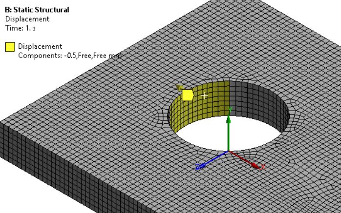
I understand we don't take stress at the boundary condition especially SPC.

What if I apply displacement across an area, is the stress at this area valid for assessment? Thanks!
 
Replies continue below

Recommended for you

Capture_hhtdnt.jpg


Hi SWComposites, I uploaded the picture... I wondering if I could just directly take the stress of the area with applied displacement or I have to model another part with contact element to the bolt hole...
 
how real is this enforced displacement ? if it is a step function then not very real so I'd average.

are you trying to simulate contact ?

another day in paradise, or is paradise one day closer ?
 
Hi rb1957, it is real displacement... I just change the geometry for illustration to avoid the conflict...

Basically, the area will be pushed to a required distance ... and we would like to see if this area will be damaged... some directly pick the stress at this area... I am thinking to model another part with contact element in between then assess the stress there...
 
ok, but is the representation of how this displacement is applied to the part realistic ? like a contact, or a sine distribution. Your sketch looks like a 120deg sector has this displacement applied, so the elements at the boundary are going to be very confused.

another day in paradise, or is paradise one day closer ?
 
What is the material?
What material model are you using?
Predicting “damage” for bearing load is a VERY complicated, difficult problem.
 
I am uploading another picture which is more relevant to my problem.

Let's say there is a beam and I press the end up to 0.5cm and if I want to assess if the area where I press it would result in any risk of failure, can I check the stress directly within that region?

The material is aluminum.

I understand that we do not take the stress at boundary condition but not sure about this


Beam_leg0vw.jpg
 
IMO, no.

FEA gives us a view into a much deeper world. In hand calcs no one asks "what is the stress 1mm away from the point load ?" 'cause everyone knows a point load is artificial.

You've applied an enforced displacement to a cantilever. Hopefully you applied the displacement to a single node (or a very small group of nodes) and not to the blue "blob" at the end of the cantilever. Displacing the entire blue area says within the blue nothing much is happening (it's all displacing the same) and at the boundary merry "hell" is happening, as one atom of Al looks at it's pal microns away and sees this instantaneous (in terms of length along the beam) displacement. I'd do a hand calc at the boundary of your enforced displacement ... shear on the cross-section. If you want to kill it with analysis, then maybe a shear lag calc from the load point.

One is tempted to ask "why FEA such a simple problem?"

another day in paradise, or is paradise one day closer ?
 
Actually, it is a snap fit design...there was damage at the point of applied displacement...

Someone from my group taking the high stress at the area where enforced displacement is applied to judge the reason of damage...but I do not feel comfortable to take the stress at where the displacement applied to... Another reason given is it is conservative but... I am still not fine with it...

Note: P is where the displacement applied...
P_ji70hx.jpg
 
if its a linear model it's hard to see how it could be unconservative.
so something is riding up the ramp, pushing the latch down, until "snap", the thing travels past the end of the ramp. If you're seeing damage, this is something I'd look into ... the impact load of the "snap".

another day in paradise, or is paradise one day closer ?
 
What is happening now, people use linear model (another thing) to look at the stress at where the displacement applied....

I don't think it is realistic yet it is claimed that conservative...
 
That snap fit part will fail at the base of the tang, not at the location where load P is applied. So no need to consider any stresses at the location of load P.
 
why wouldn't a linear model be conservative ? do you think dynamic effects play a role ?

agree with SWC, the critical section is most likely the fixed end of the cantilever.

another day in paradise, or is paradise one day closer ?
 
I think I should not say linear model is not conservative but I am skeptical at taking the stress at enforced displacement region (Area A)..

Yes... the failure should be at the root but there was some damage at the Area A...the team interpret the high stress at Area A resulted the damage ... but I think the high stress is due to displacement


Capture_omo74r.jpg
 
yes, the stress from the FEM will be high in the region of the load. I agree you can say that the FEM is unreliable in the region of the load. This particular problem could the better solved by taking the load (enforced displacement) as a function of time, as the stop travels up the ramp. You could then model the contact better. All this to show that the contact area is not critical ... except maybe for contact stress.

another day in paradise, or is paradise one day closer ?
 
However, the team would interpret it as conservative than unrealistic...
 
there are times when "the team" knows less than some of it's members !? note, I described the FEM as "conservative and unreliable".

When it's your team you can tell them how to do it "right" !

It is one of the things I've noticed over the years ... we seems to be surrounding calculation for "tech pubs" ... very nice stories, full of pictures and nice formatting (at the expense of content and understanding). What I've described as "building palaces in the swamps". FEM produces numbers and pictures and some people feel that these are "revelations".

another day in paradise, or is paradise one day closer ?
 
I do not think I have even the beginning of any understanding of what the "damage" may be. Chipping of some, or all of the Dec 18 sharp edge or one of Dec 19's beveled edges? Scuffing of some portions of Area A.? Probably something else altogether. Good, clear, close up Pictures would be so much better than words will ever be.

The rubbing/sliding materials could play a big role in "Damage." Some Stainless steel on Stainless Steel combos are VERY prone to destructive galling if the contact stress exceeds a few ksi.

I figure during assembly, Just before the cantilever snaps home, area A will be tipped relative to whatever the opposing surface is. So considering the entire Area A being instantaneously involved in anything connected with assembly is definitely NOT conservative. Maybe 100 X NOT conservative. Pictures of the damage of several samples would be REQUIRED to understand this

How are the several details of the interface of the mating snap interface holding up? Any chamfers, or lack of them, on the edge of the mating snap interface.
 
What I have discovered is there seems to be a lack of understanding of materials in the occupation of engineering, it has been that way for the last 100 years at least.
In other words your trying to apply tons of math and computer time where just simple knowledge of materials to use will fix the problem.
There have been thousands of engineering failures due to wrong material choices, especially in the transportation industry's.
Toss out the computer and find an old mechanic or machinist to fix it for you.
 
Status
Not open for further replies.

Part and Inventory Search

Sponsor