Eng-Tips is the largest engineering community on the Internet

Intelligent Work Forums for Engineering Professionals

Stress at junction of plate and solid elements with skins not realistic. Is this normal?

Status
Not open for further replies.

Mark172

Aerospace
Aug 26, 2008
43
0
6
US
I am somewhat new to using skin elements to account for moments at the junction between plates and solids, but I believe I'm doing it correctly. Yet the stress distributions I see have stark discontinuities and are nothing like what I would expect in the real world. My intuition is confirmed when re-modeling in 100% tet solids. Furthermore the max stress predicted by the hex/plate/skin combo is ~30% less than the tet model.

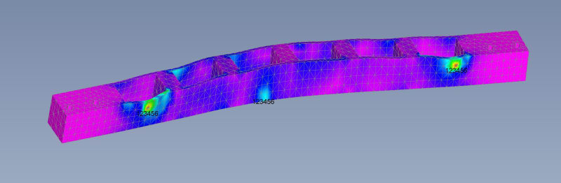
Stress results one would intuitively expect, modeled with all solid tets:
2024-4-3_5_gfafuj.jpg


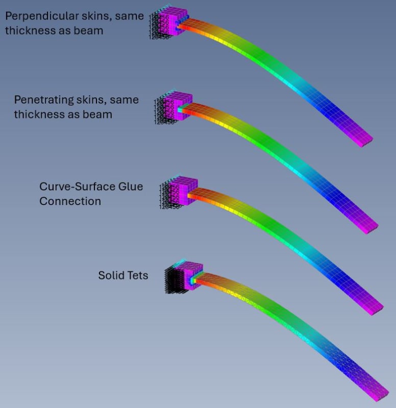
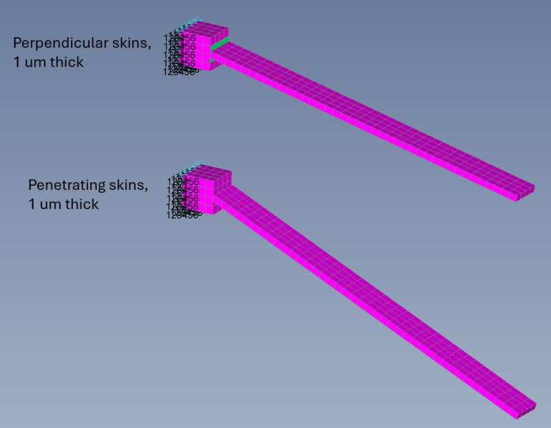
Stress results using plates and hex solids skinned with thin plates:
2024-4-3_2_vunx1g.jpg


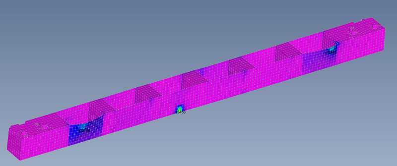
When I think about it, it makes sense that an extremely thin plate element would bend easily and you would see huge stress discontinuities, despite constraining the moments. But somehow I was under the impression that skin elements are a perfectly fine way to build efficient models that give mostly realistic stress distributions. Was I wrong to assume this? Am I somehow setting up the skin elements incorrectly?
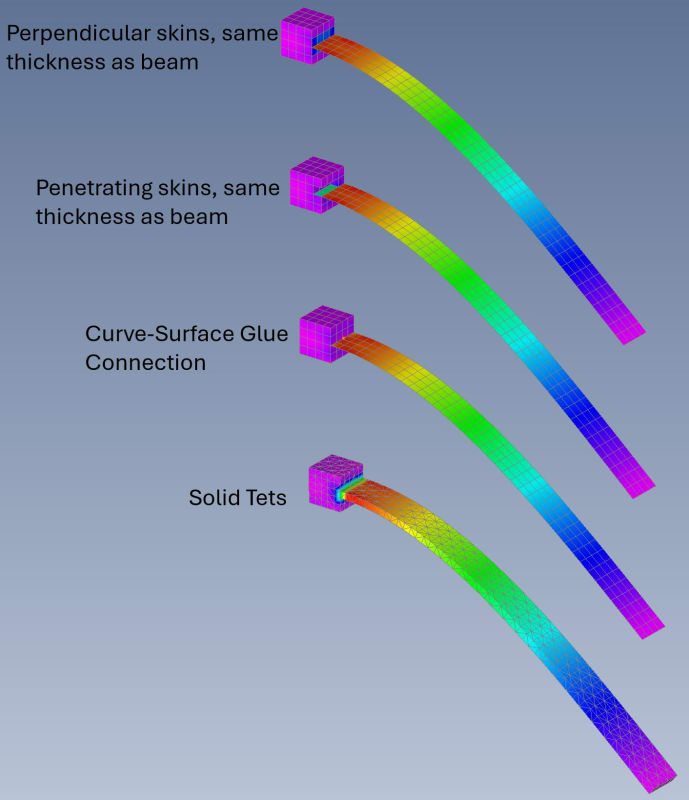
 
Replies continue below

Recommended for you

what I suggest doing is modelling a simple cantilever beam with both approaches. sort out any differences with a model that you can predict the stresses using close form solutions.

the difference might come down to the material properties and thicknesses that you are applying to the plate elements, and to the solid elements. provide more details.
 
My specific question pertained to "skinning" solid elements, a common method of connecting shells and solids to constrain all 6 DOFs (solids do not constrain moments/rotations). Skinning is performed by creating plates on top of solids to "skin" them, thereby using the plate that shares nodes on one of the solid faces to constrain the rotational DOFs at the junction with plate elements. A related method of constraining rotation is to penetrate plates into the solid surface, providing >3 points in a plane to constrain rotation. This isn't skinning per se but I have examined it here, too.

The question - does skinning provide a realistic distribution of stresses? And how does one correctly apply the skinning method (particularly in terms of skin thickness)?

The short answer I've come to is that skinning does NOT provide realistic stress distributions nor values. Very thin skins, on the order of 1 um as I've seen commonly used, do not provide accurate *deflection* let alone stress predictions. In fact they often do not prevent pivot errors and deform well past elastic assumptions. I surmise that these are ONLY useful to prevent pivot ratio errors in some situations. Skins of equal thickness to the adjoined plates appear to approximate true deflection, but do not predict stress distributions remotely accurate (and add mass). Penetrating plates of equal thickness to adjoined members gets closer, showing a somewhat representative stress on the penetrating plates, but does not transmit this stress in a realistic fashion to the solid. Similarly with glued connections.

In conclusion, skinning should be used with extreme caution and any stresses reported in the vicinity of skin connections should be viewed with a large amount of skepticism. The best method for stress prediction seems to be penetrating plates, but even so is little more than a very rough approximation.

2024-4-3_4_jmpfma.jpg


2024-4-3_3_bwr5ev.jpg
 
TET elements ... are you using TET4s (don't) or TET10s ?

have you fully constrained the three "glowing" points ? why ??

This is a linear FEA ? So peak stresses are unreal ... in your case a very minor amount of plasticity would occur. And the best approach would be to hand calc the interface forces.


"Hoffen wir mal, dass alles gut geht !"
General Paulus, Nov 1942, outside Stalingrad after the launch of Operation Uranus.
 
"skinning solid elements" ? to quote Monty Python (as I do) ... what kind of talk is that ?

"Hoffen wir mal, dass alles gut geht !"
General Paulus, Nov 1942, outside Stalingrad after the launch of Operation Uranus.
 
The tet example on the bottom of image 1 is using tet10s. The other examples use hexes (8 node bricks) for the foundation cube, because connecting plates to hexes is what I'm most interested in.

I'm not sure which glowing points you're referring to. The only nodes constrained are the "wall" at the far side of the cubes that are acting as the foundations for the cantilevered plates.

Why do people skin solids? That's what I'm trying to figure out. I *thought* it was a method for constraining rotations at junctions between solids and plates, but it doesn't seem to do this very well and produces spurious stresses.

We are building fairly large models of spacecraft for dynamic analyses, and the models we get from vendors have membranes or plates as skin elements all over the solids at the junctions to plate elements. I'm interested in understanding the accuracy of the stress predictions in those areas because we use these models for general assessments of our buses. This exercise makes me question how much to trust the stress results. I was somewhat skeptical before, now I am somewhat worried.
 
Wait, your initial post asked about connecting plate elements into a solid element area.

But your cantilever models show two solid element sections connected. What kind of solid elements are you using? If just std 8 noded hex solids, then those aren’t very good in bending for the beam section. Why not model the cantilever beam portion with plate elements?

Anyway, as mentioned above, the stresses at the junction between the thin section and thick section in either model will not be correct, due to local stress concentrations due to the abrupt thickness change.

 
I'm sorry, let me upload better pictures. The cantilevered beams are made of plates, the foundation cubes are solids. I had toggled "view thickness" in FEMAP, which makes the plates look like solids. Note that I have removed 3 solid elements from the second example (penetrating skins) to show the reported stresses on those penetrating elements.

Understood that the stresses won't be "correct" at junctions due to stress concentrations. We're looking for an 85% solution here, not 99% (as far as stresses are concerned).

2024-4-3_6_ccprmh.jpg
 
Ok, those pictures make more senses.

In the real world no part looks like the idealization of a plate attached to a rectangular section. There will always be a fillet radius or something. With the refinement of your FEMs, there is no way to get accurate stresses directly from the FEM at the junction. Just accept it. Exclude the elements at the junction from the stress plots. Then either a) use a classical stress concentration factor applied to the forces from the plate element adjacent to the solid to get local stresses, or b) (not recommended) make a very detailed FEM at the junctions.

All of the cantilever beam modelling methods you show appear to be ok for the stresses away from the junction (assuming you are using 10 tets; do not use 4 noded tets, particularly in bending).
 
Thanks for the thoughts. I will think on it. The penetrating plate elements (2nd example from top) seem to do an ok job of showing ballpark stresses. Perhaps we can use the results of FEMs built like this to point us to locations where we need to perform classical calculations.
 
maybe I'm being thick, but what does "penetrating skins" and "perpendicular skins" mean ?

To my way of thinking you can model with solid elements (hang the computing time), or you can model with 2D skins (where the thickness is part of the element geometry, so the elements are on the mid-plane).

I guess you could model the upper 1/2 and the lower 1/2 as 2D elements, but I don't know why, and joining them together would be "tricky".
Maybe you could model as a sandwich panel (facings and core), but why ?

With you solid model, how many elements through the thickness ?

"Hoffen wir mal, dass alles gut geht !"
General Paulus, Nov 1942, outside Stalingrad after the launch of Operation Uranus.
 
Dear Mark,
Do not get creazy, the beter method to joint shell to solid is simply edge-to-face GLUE effect, forget skining, see my blog:

edge_to_surface_glue_r6yrbd.png


Glue is a simple and effective method to join meshes which are dissimilar. It correctly transfers displacement and loads resulting in an accurate strain and stress condition at the interface. The grid points on glued edges and surfaces do not need to be coincident.
Glue creates stiff springs or a weld like connection to prevent relative motion in all directions.

Best regards,
Blas.

~~~~~~~~~~~~~~~~~~~~~~
Blas Molero Hidalgo
Ingeniero Industrial
Director

IBERISA
48004 BILBAO (SPAIN)
WEB: Blog de FEMAP & NX Nastran:
 
Status
Not open for further replies.
Back
Top