Eng-Tips is the largest engineering community on the Internet

Intelligent Work Forums for Engineering Professionals

  • Congratulations waross on being selected by the Tek-Tips community for having the most helpful posts in the forums last week. Way to Go!

Stress at middle of flange is not symmetric

Status
Not open for further replies.

AAA1993

Civil/Environmental
Mar 9, 2023
18
0
0
HK
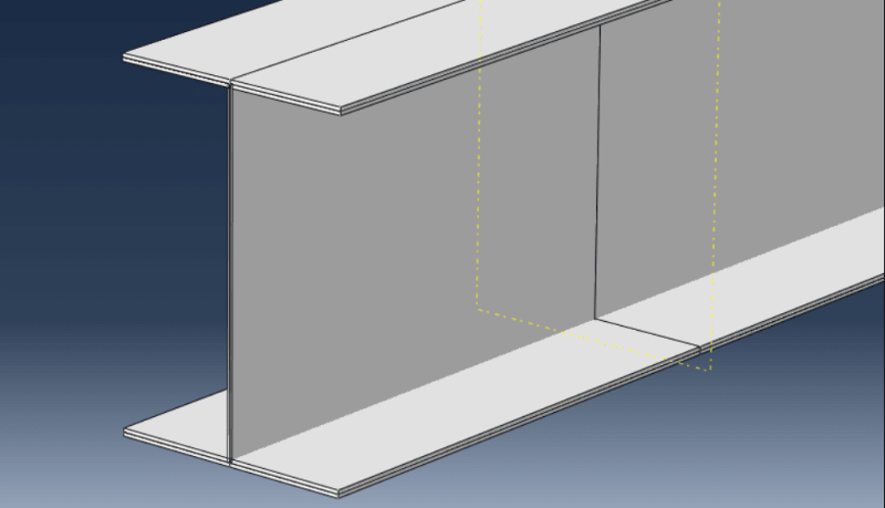
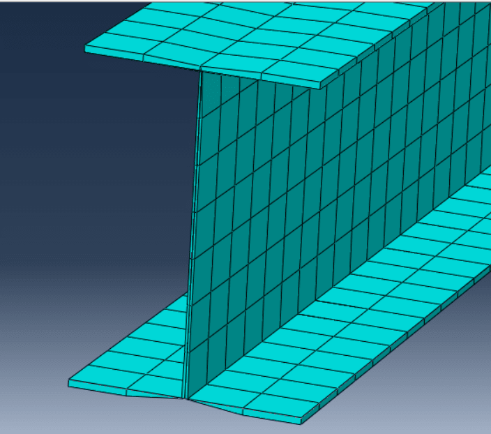
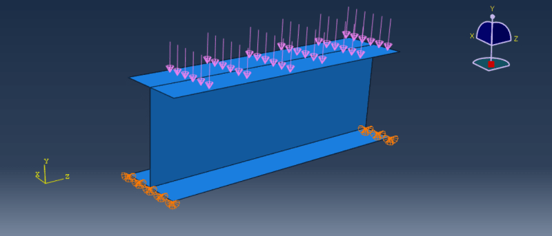
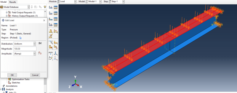
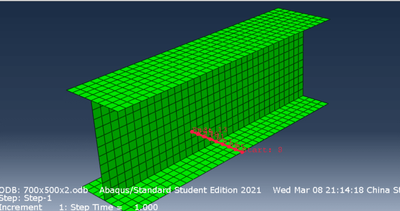
Hi all,I have tried to do simply supported one span I beam under uniform distributed load. Then extract s11 by defining path at bottom flange. However,

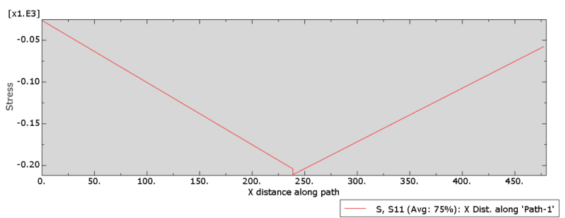
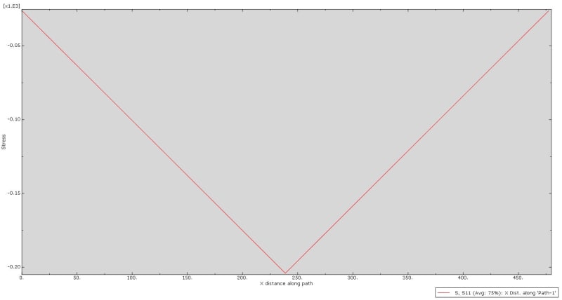
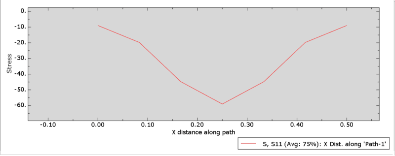
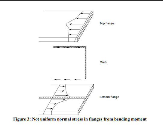
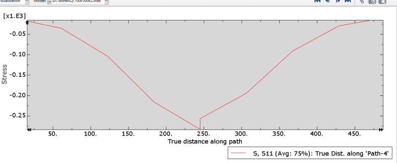
1.The stress in x-dir s11 is not symmetric along flange, there is sudden increase in stress at RHS of middle flange (i understand there would be shear lag effect which cause ununiform stress but the stress along flange should be symmetric and no sudden increase in my understanding)
stress_hqhhkr.png


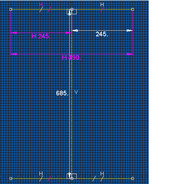
2. The section I drew on each size is 250mm (by using adding dimension), however sum up value is 490mm
section_kqrm0h.png


Grateful if you could provide help. Thanks
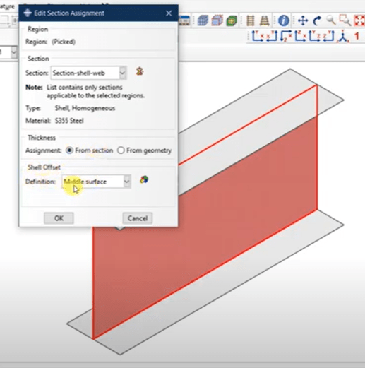
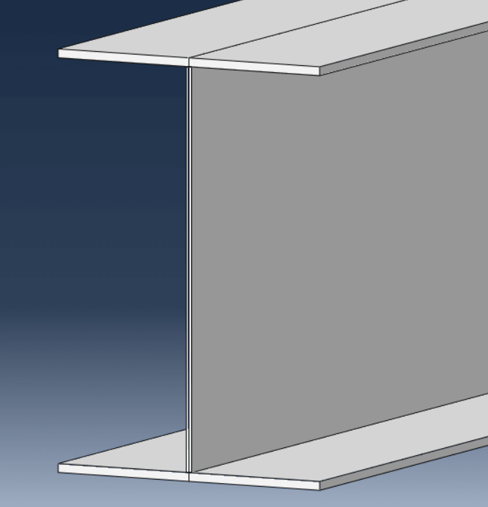
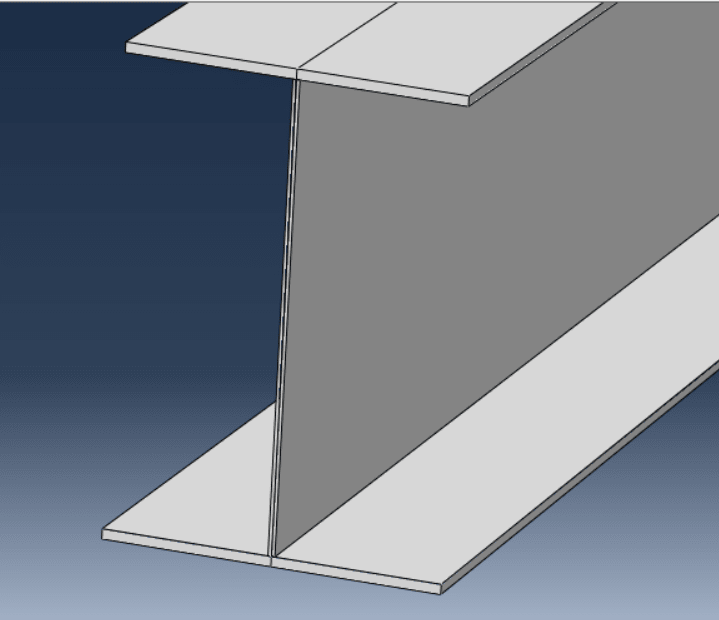
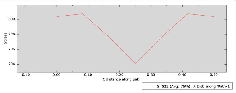
load_w5za1d.png
path_nklpch.png
 
Replies continue below

Recommended for you

Offsetting the shell sections applied to the flanges should help. Just make sure that normals are consistent first.

Regarding the sketch, I'm not sure what you are talking about. 245+245=490 so it's fine unless you wanted those sides to be 250 mm long instead of 245 mm long. In such a case you can just edit that dimension (before doing that make sure that the sketch is properly constrained).
 
Thanks for your prompt response.

1. When i built up this model, i alreay apply shell offest to create flange and web thickness (kind of like below image)
offset_gf8h1x.png


But i am no sure how to make sure the normals are consistent. Becacuse i kind of new in Abaqus.

2.Sorry for my bad math, i make stupid mistake here.[lol] You are right, the section is correct.
 
I just wonder there may be something wrong at the joint between flange and web. But the extrude view (see below image) is kind of normal to me.

1_hrjisf.png


I made a parition at the mid span so that I can create path and extract stress. I know it is kind of stupid but i dont know if there is proper way to get the stress at mid span.
 
Offset should be set to top or bottom surface for the flanges so that they don’t interfere with the web. Thickness visualization will show you if it’s ok.

shell_offset_cdey4z.png
 
Thanks for your response. I tried your method. But there is still sudden increase in stress (but at other side this time) and the stress at two end are different.
stress2_m7jgjo.png


extrude_view_ndoe4z.png


Also I found that mesh in extrude view is strange (taper close to the centerline), i dont know if it is normal.

mesh_lmjsmw.png
 
Well, I get the correct distribution with those changes, double-check your settings.

path_plot_fjz5rr.jpg


Regarding that shell thickness visualization - it should be correct if you enable it in the Visualization module.
 
Thanks. I did several trials, finally have the following stress diaphragm

s11_p1zsrw.png


s22_lgdvo8.png


setup_srtrwi.png


But dont know why s22 stress pattern is like that. Not sure if it is correct or not.

I also have some question.

Q1: I found that if I pin only bottom flange vs both top and bottom flange, the S11 and S22 stress diaphragm patterns are vice versa. I just wonder if i want to simulate simply support beam, should I just pin bottom flange like below image?

support_hawid2.png


Q2:I wanna get the stress same as the direction in below image, should I take S11 in model instead of S22?
normal_stress_t8omji.png


Sorry for so many questions.
 
Status
Not open for further replies.
Back
Top