Continue to Site

Eng-Tips is the largest engineering community on the Internet

Intelligent Work Forums for Engineering Professionals

  • Congratulations KootK on being selected by the Eng-Tips community for having the most helpful posts in the forums last week. Way to Go!

Stress-Strain Curve Development

Status
Not open for further replies.

RJW000

Mechanical
Jan 14, 2021
21
Hello, I am following Annex 3D.3 of VIII-2 for developing a stress-strain curve to be used in an Elastic-Plastic analysis and had a few questions.

Currently, I am doing the following (true plastic strain plot only since I am using Abaqus):
1) Solve for stress at the proportional limit which is when the true plastic strain (gamma1 + gamma2) equals e_p.
2) Plot from this stress to true UTS in small increments
3) The curve from 0 to e_p follows a slope of Sys / E

Is this the correct approach? I've attached a picture of a curve I generated.
[ul]
[li]Sys = 38 ksi, UTS = 70 ksi[/li]
[li]Stress @ Prop Limit = 20,620 psi and true UTS = 92,091 psi[/li]
[/ul]

If one did not follow these steps and ignored the proportional limit, could it be unconservative to use a material curve from the engineering yield stress to the true UTS?
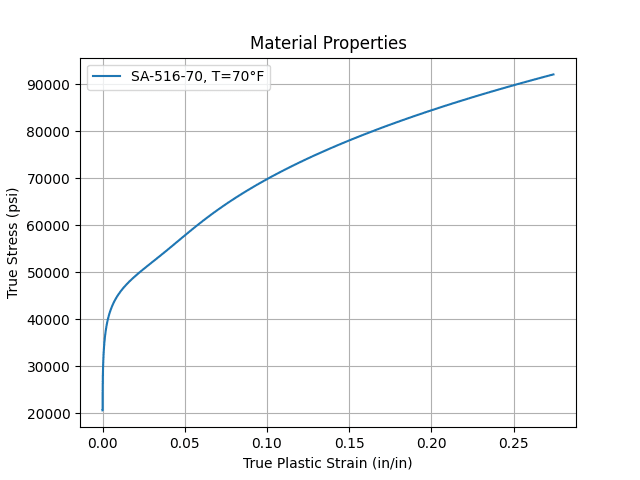
Figure_1_cv4yqc.png
 
Replies continue below

Recommended for you

The curve is usually only inputted to the FEA program from the proportional limit. Elastic properties are covered seperately with the young's modulus (at least with ANSYS)

The curve shown isn't correct, the true UTS is too low but it is roughly what needs to be put into an FE program.

Starting the curve after the proprotional limit would matter as it would give incorrect plastic strains, effecting your local failure criteria.
 
I agree with SSCon.

I will also add the following - you will miss a lot of plastic strain between the proportional limit and the engineering yield if you ignored the proportional limit.
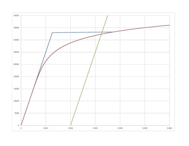
stress-strain_curves_fnqgiw.jpg


(Feel free to ignore the green line in this plot - it shows how the 0.2% offset method is used to set the engineering yield stress (give or take a small amount).

The red line is the full curve from 3-D. The blue line is the curve that you would get if you started the stress-strain curve at the engineering yield. As you can see, below the engineering yield, you would miss a lot of plasticity. That can be an issue for both the local failure mode, but also any service limits.

Whether that makes it unconservative or not is more a call for the individual engineer. However, the Code rules are very clear about how to form the curve, so there's that...

[edit]Oh yes - and for your example, the true UTS would be correct if your engineering ultimate were 70ksi. If it were 80 ksi, then the true UTS would be 109,621 psi. However, I agree with your proportional limit.[/edit]
 
Oops, I had a typo in the original post. I meant to specify that I used an engineering UTS of 70 ksi not 80 ksi.

Thanks for the explanation TGS4, looks like I implemented it correctly.
 
Status
Not open for further replies.

Part and Inventory Search

Sponsor