Continue to Site

Eng-Tips is the largest engineering community on the Internet

Intelligent Work Forums for Engineering Professionals

  • Congratulations KootK on being selected by the Eng-Tips community for having the most helpful posts in the forums last week. Way to Go!

Stresses in a very wide T shape

r.borghino

Structural
Nov 25, 2024
7
Hi,
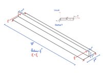
I am working on a problem where I have a roughly "T" shape profile (inverted) where I am applying two equal point loads to the top of the single leg. I am trying to evaluate stresses on the flat plate caused by the cantilever leg. I usually simplify this problem and simply assume a flat plate with a moment applied at midspan. However, I'd like to make a more "real" analysis without going into FEM. I've looked through Roark and other sources but to no avail. I am definitely missing something... do you have any help or insights to spare? (is it even worth the effort?) Thanks! T Profile.jpg
 
Replies continue below

Recommended for you

The best approach will depend on:

1) What specifically you would like to achieve as a design goal and;

2) What aspects of behavior your are willing to consider trivial.

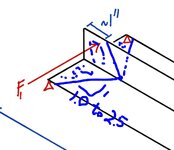
An effective length as shown below would appeal to me assuming that the dominant concern is warping torsion.

c01.JPG
 
What sort of force magnitudes are we talking here? Depending on the load there might be some simplifications that you can make without losing too much sleep on it. Otherwise FEA is the way to go.

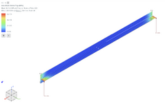
Here's a quick model with F1=F2=1kN just to illustrate what kind of stress distribtion you'd expect; this is in line with what KootK has shown above.

2.png

What I'm seeing is that the web of the T is getting a stress concentration on the end which could suggest some form of buckling, long before the load fails towards the middle of the plate.
 
Last edited:
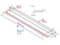
Thanks for that, I realized I over-simplified the analysis a bit (one of the edges of the bottom plate is continuously braced, the other end is free). I add an improved sketch.

Deflection is not a concern. The design objective is to avoid local yielding at the point where the leg meets the plate.
What sort of force magnitudes are we talking here? Depending on the load there might be some simplifications that you can make without losing too much sleep on it. Otherwise FEA is the way to go.
Roughly 1-1.3 kips. Loads are relatively low, but the shape is pretty slender too. This one is thicker than usual at 1/4". Other T shapes I've worked with are 1/8".

T Shape 2.jpg
 
Adding the supports to the braced backside helps unload the flanges a bit but you still get that same stress concentration on the web "T". Take it with a grain of salt, but with your loads in and modeled as 1/4" thick the maximum stress in my FEA is exceeding your typical 44W steel.

2.png
 
Deflection is not a concern. The design objective is to avoid local yielding at the point where the leg meets the plate.

Are you sure that you need to avoid "hot spot" local yielding? In many situations, I would be willing to let the stem yield locally and redistribute.
 
Adding the supports to the braced backside helps unload the flanges a bit but you still get that same stress concentration on the web "T". Take it with a grain of salt, but with your loads in and modeled as 1/4" thick the maximum stress in my FEA is exceeding your typical 44W steel.
Screenshot 2024-12-10 at 3.41.48 p.m..png
Performed a quick FEA and yes, same results. Using the usual approach with the moment at center of beam gives me a much higher stress at the plate.
 
Are you sure that you need to avoid "hot spot" local yielding? In many situations, I would be willing to let the stem yield locally and redistribute.
I'll think about that. This is a curtain wall application. Usually anything that yields would not pass muster because any small permanent deformations can compromise the water management. The load is a wind load reaction so it needs to receive that point load acting alternately in both directions repeatedly throughout the service life (admittedly in much lower intensities).

So if I understood correctly your approach would be to calculate or estimate an "effective length"?
 
Your shape likely will buckle under load.
Read about members in bending. In this case you need to check for buckling since it is essentially a plate unbraced. Add gussets to strengthen the section at the loads.
 

Part and Inventory Search

Sponsor