Eng-Tips is the largest engineering community on the Internet

Intelligent Work Forums for Engineering Professionals

  • Congratulations waross on being selected by the Eng-Tips community for having the most helpful posts in the forums last week. Way to Go!

Strip footing with point loads 3

Status
Not open for further replies.

DetroitJon

Structural
Apr 26, 2016
6
US
I'm working on a strip footing for a small commercial building. Soils are medium-dense sand with a bearing capacity of 2,500 psf for strip footings and a max strip footing width of 2'. The building footprint is 28' wide and while I can extend the footing on one side about two or three feet, the other side is constrained by a retaining wall that the footing will run into the heel of. The loading on the footing is two 36k column loads on each end and 16k in the two spots located 8' from each end.

I'm looking at this as a ~100k load on a footing with a 150k capacity (2'x30x'2.5ksf) so it's possible at least. The geotech eng. gave me a modulus of subgrade reaction of 150 pci for engineered fill on site, though he might bump that up since we're setting this on native soil. I know the footing is in negative bending and will need a bunch of steel at the top in addition to the steel at the bottom. I'm trying to figure out how to analyze this to get some efficiency with footing depth vs steel content. Especially with the sandy soils, are uncoupled springs a good (enough) way to model the soil? Do I need to go full FEA on this? I was thinking about setting the concrete depth to avoid needing stirrups for shear as this is in a smaller town (not Detroit) and competent labor is a little hard to come by.
 
Replies continue below

Recommended for you

If you have software like Enercalc, you can look at it as a beam on a elastic foundation (assuming I understand this correctly). You can set up something similar in FEA software like STAAD.

There are hand solutions out there.....but I could do something like this in STAAD faster. (Checking various scenarios of spring constants, etc.)
 
Calculate the soil pressure below your footing [100k / (2'x30') = 1.66 ksf] and design the cantilevered portion of the footing for the factored pressure. That will give you the area of steel in the short direction. To get the area of steel in the long direction, turn the whole thing upside down and apply the pressure to your footing as if it were a continuous beam w/ 4 supports (each support being your column load). Not quite as fancy as FEA, but it works. (Tip: avoid stirrups in strip footings at all costs......your name will be cussed by the rod busters).
Nice to hear from a fellow Detroiter!
 
MC: that's the quick and dirty way... and works well.

Dik
 
MC: What do you mean by short/long direction? The 2' direction? I hadn't thought about that, was imagining a deeper beam (~2') but I guess with some short bars I could get away with a 12" depth with some short steel.

But the stiffness of the footing is an issue right? If I turn the beam upside down and apply an even pressure, I get most of the load on the center two supports, when really the load is coming from the outside supports. It make a big difference in the deflected shape when I turn it back over.

Wasn't expecting to see another Detroiter on here, you in the city or out in the burbs?
 
The simple but conservative solution for bending load on the footing would seem to be assuming a uniform or linear varying bearing pressure on the soil, whatever is required to produce equilibrium with the column loads. Then it becomes essentially a fairly simple 3-span beam problem. Since the beam isn't complete rigid, the actual load on the soil will vary, with higher pressures near the columns where the deflection is the the greatest, so the actual moments will be slightly smaller than the calculated moments. Exactly how much smaller is a function of the elastic modulus of the soil and the flexibility of the footing, which of course would be revealed by a more detailed analysis, such as an FEA or soil spring model.

Considering the cost difference of a little additional reinforcement compared to the time it would take to do a more in-depth analysis, I think the simpler analysis is the more cost-effective solution for a project of this size. If you were doing 20 or 50 buildings like this, then refining the analysis would probably be worthwhile.

Edit: I seem to be repeating Motorcity's post, but I was apparently still writing when it was posted.
 
If the footing ends up deeper than you would like to accommodate the full shear without stirrups, if you have the room, you could consider extending the length of the footing beyond the corner columns, so that the 36 kip shear load is distributed to both sides of the column. Now you have a 3-span beam with cantilevers, which may make the uniform load model work, also. A 30% or so longer footing that's half as deep might even save a little dough.
 
DetroitJon said:
But the stiffness of the footing is an issue right?

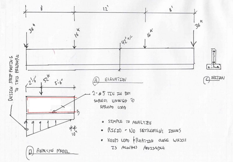
Yes, it is. The issue really. At the proportions that I expect here, I feel that it's too aggressive to attempt to utilize a uniform spread across the whole 28' length. To the extent that you develop curvature in the footing & stem wall, you will have additional settlement to contend with. And settlement is usually the main concern with spread footings. Additionally, it's generally good practice to keep your resisting loads as close as practical to your applied loads. I've proposed an alternative approach below that I believe would be preferable. You might need a wider footings but you'll also need a whole lot less top steel & design time. And be sure to include reasonable provisions for patterning of the column loads. I'd be more amenable to a full uniform load spread if we were talking about a full basement condition.

c01_o1owrf.jpg


I like to debate structural engineering theory -- a lot. If I challenge you on something, know that I'm doing so because I respect your opinion enough to either change it or adopt it.
 
DetroitJon - when I read your post, I was envisioning a narrow strip, say 2' wide with a stem wall above centered on the strip. It sounds like you are thinking more along the lines of a grade beam which would work equally well. Stiffness of any flexural element is an issue, and as you noted, it is reflected in the deflection. You would probably want to make the section deeper to overcome excessive deflection. Another thought, perhaps just design it as small spread footing below each column, connected by a "filler" strip of concrete. So for your 36k load, you would only need a 2'x7' spread footing to achieve 2.5 ksf. For something like this, I'm not a fan of FEA because I think it misleads you into a false sense of accuracy.

I worked downtown for a number of years, long before the current revitalization. And to be honest, its very disappointing that it all happened after I left. As you probably know, its becoming very vibrant and more of a tourist destination. Glad to see it coming back. Of course now I am watching it all happen from the suburbs.
 

It is better to analyze the beam with FEA software. You know soil modulus of subgrade reaction of 150 pci and the foundation width is 2 feet. Assume simulate soil springs along the foundation at each feet, the spring stiffness k=150*12*24/1000=43.2k/in.
 
MC said:
For something like this, I'm not a fan of FEA because I think it misleads you into a false sense of accuracy.

Opinions are as belly buttons but, for what it's worth, this is how I feel verbatim. Accuracy aside, you'd have a hard time convincing me that any building 28' wide deserves FEM anything. Not unless your're getting $5/SF, which you're not.

I like to debate structural engineering theory -- a lot. If I challenge you on something, know that I'm doing so because I respect your opinion enough to either change it or adopt it.
 
Kootk - sometimes engineers just get caught up in trying to kill an ant with a sledge hammer (FEA) instead of a fly swatter (half a page of hand calcs). I fall victim myself at times. That said, I feel like somewhere out there, there is a huge cash cow that I am missing out on where the clients have budgets I would cut off a finger for.
 
I doubt the FEA should take more half an hour to do, but I'd probably just use the conservative assumption of uniformly distributed soil loading, because it's a safe lower bound solution.
 
MC said:
That said, I feel like somewhere out there, there is a huge cash cow that I am missing out on where the clients have budgets I would cut off a finger for.

For the most part, there isn't. I've worked for a couple of firms that might be considered "top tier". My experience of that has been:

1) Fees are often large, because projects are large, but margins are still pretty tight. Often large project fees get even tighter as those contracts are highly desired.

2) Where fees are generous, I see designers getting wasteful and budgets getting blown. Dynamic wind analyses on little entry canopies just because the geometry's a bit weird etc.

3) Because our work is regrettably commoditized, slightly generous fees are often garnered via expensive marketing and business development efforts. This ends up just being a wash sometimes. The extra fee just goes to support the extra marketing overhead. It's a good strategy for getting high profile work though.

I like to debate structural engineering theory -- a lot. If I challenge you on something, know that I'm doing so because I respect your opinion enough to either change it or adopt it.
 
canwesteng said:
I doubt the FEA should take more half an hour to do

Just checking the FEA should take that long.

I like to debate structural engineering theory -- a lot. If I challenge you on something, know that I'm doing so because I respect your opinion enough to either change it or adopt it.
 
The Beam on Elastic Foundation module in ENERCALC Structural Engineering Library (as mentioned by WARose) is an easy way to handle a situation like this without having to set up an FEM. It will allow you to optimize the cross-sectional dimensions of the grade beam, study the idea of avoiding shear reinforcing, and verify soil pressures and deflections.

Director of Technical Services
ENERCALC, Inc.
Web:
 
Status
Not open for further replies.

Part and Inventory Search

Sponsor

Back
Top