Eng-Tips is the largest engineering community on the Internet

Intelligent Work Forums for Engineering Professionals

  • Congratulations waross on being selected by the Eng-Tips community for having the most helpful posts in the forums last week. Way to Go!

Structural Analysis on a Truck Body Main Runner Beam.

Status
Not open for further replies.

Dyrall

Mechanical
Apr 5, 2022
4
AU
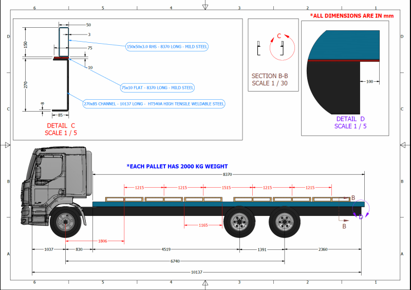
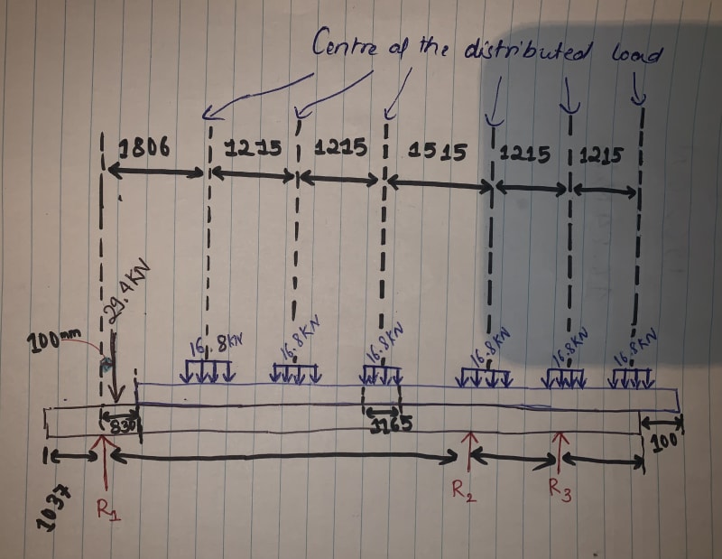
Hi guys, I am trying to do a structural analysis with hand calculation on the main runner that sit on the top of the chassis frame of the truck. 6 pallets are placed at the top of the main runner as shown in the picture. Each pallet has distributed load of 2000 Kg. I want to draw a sheer force and moment diagram and find the maximum deflection and sheer stress on the main runner beam, however I am stuck on FBD. The main runner is 150x50x3 Rectangular Hollow Section which 8370 mm long. More information available on the picture. Thank you in advance. Your help is greatly appreciated.
MAIN_RUNNER_ANALYSIS_ylq39k.png
 
Replies continue below

Recommended for you

Dyrall,

What is the problem? I would think that you have a maximum, equally distributed load, based on your rated load capacity. After that, you have to anticipate people not loading your truck properly. Be creative.

--
JHG
 
Hi drawoh, thank you for your reply. I am unable to draw a free body diagram. I am confused, when analysing only the main runner 150x50x3 RHS( Blue beam), what the reaction force would be? Would it be distributed uniform or non-uniform reaction? Do I need to consider the Chassis frame deflection or do I consider chassis frame as rigid and do the calculation(as chassis frame is already rated to carry necessary load by the manufacturer).
 
If you can't draw an FBD then how on earth could you trust any further analysis that you do? Sorry to pile on but the FBD is merely the first step in analysing a beam.

You can't analyse the blue beam in isolation, you need to model (in a loose sense) the entire frame

You do need to make some assumptions about the load split between the two rear axles, which is dependent on the suspension. You'll probably assume 50/50.

You also seem to be ignoring the dead load from the cab, which is of the order of one of your pallets.


Cheers

Greg Locock


New here? Try reading these, they might help FAQ731-376
 
This sounds a lot like a homework problem- for an actual truck, I assume this would be a dynamics/vibration problem, not a statics problem.
 
The fixity of the blue bema to the ladder chassis is also an issue, is it free to slide (probably not) or securely fastened at several places along its length- Probably. Or welded all the way along- probably not.


Cheers

Greg Locock


New here? Try reading these, they might help FAQ731-376
 
Thank you so much for replying. Please pardon my ignorance.
I have attempted a Free Body Diagram. I am trying to do a static analysis on the beam.
Qty 9, 50x5 -250 long mild steel flats are welded on to the blue(all flats are placed 900mm apart - centre to centre) and the plates are fastened to the chassis.
Please suggest if I am going in right direction. Thanks again.


38650E19-16A0-47CA-8D0B-A9ADF680C08B_vlwhql.jpg
 
Hi Greg, I included 29.4 KN, the dead load of cab as a point load after your suggestion. My apologies the 16.8 KN is actually 16.8 KN/m (distributed load on the pallet). The dimension of the pallet is 1.165 m long so for 2000kg load on the pallet gives 16.8 KN/m.

Regards
Dyrall
 
Status
Not open for further replies.

Part and Inventory Search

Sponsor

Back
Top