Eng-Tips is the largest engineering community on the Internet

Intelligent Work Forums for Engineering Professionals

Structural analysis with winch, wire rope, and sheaves

Status
Not open for further replies.

bootlegend

Structural
Mar 1, 2005
289
0
16
US
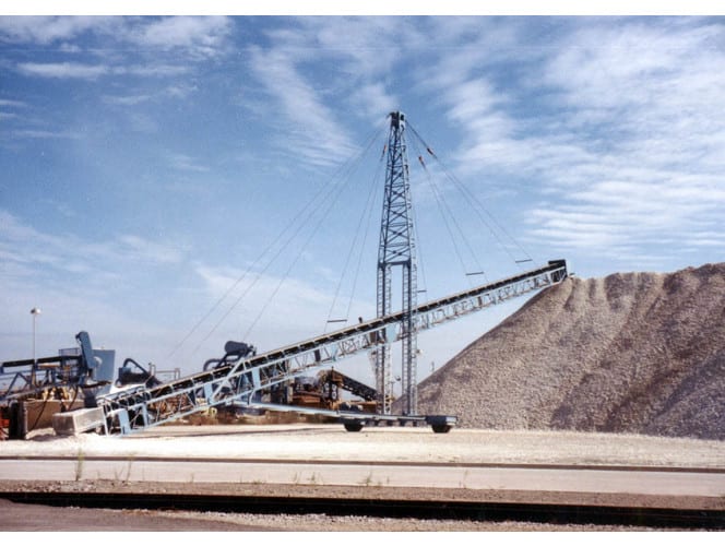
I'm looking at the following scenario, conceptual sketch attached. A conveyor is pinned at the tail and will be inclined/declined using a winch and wire rope system. The wire rope will attach at at least a couple points along the conveyor and will be supported from a central mast that will carry the resulting load. I have designed a couple of these in the past by assuming rigid support points to get an approximate load at each point and determine a number of line parts required at each point. Using these I can solve for the tension value in the FBD to balance the system for each load case (DL, LL, etc). Then I've modeled the conveyor as a beam in RISA, applied the previously calculated support point reactions as point loads, and added a roller at the high end so that I have a simply supported beam. This reaction should be zero. This has worked but it is time consuming even for one situation, but with multiple load cases, multiple possible inclines or declines, and multiple considerations of support point locations, it takes a lot of time.

Modeling the supporting cables directly would be a lot more simple, but since it's a single cable and all the supports are relative to line tension T and parts of line I can't simply attach them to the upper mast support point because the relationship isn't maintained.

Anyone know of any software that might simplify the analysis of wire rope and pulley situations with multiple lift points?

 
 https://files.engineering.com/getfile.aspx?folder=19fc573d-f98e-4be9-9799-47acde3d859a&file=lift_sketch.pdf
Replies continue below

Recommended for you

Why would C have 2 cables? and why would A and B be 10x... just curious.

-----*****-----
So strange to see the singularity approaching while the entire planet is rapidly turning into a hellscape. -John Coates

-Dik
 
Dik,

Winch is located at C in the sketch. I was planning on reaving multiple part line at points A and B based on tributary load and then going back over the support to the winch location and anchoring on the frame or such to get 2T at that point.

 
FBD should show load (weight ?) on conveyor.

don't you need different translation at A and B (as they pivot about C) ?

Are you saying there is a 5:1 ratio between the conveyor pick ups and the anchor line ?

Is the assumption of a static conveyor conservative ? I'd've thought (without much thought !?) that the moving conveyor would've increased the support loads ?

"Hoffen wir mal, dass alles gut geht !"
General Paulus, Nov 1942, outside Stalingrad after the launch of Operation Uranus.
 
Maybe I am missing something here, but...

Add the conveyor's self weight to your FBD (as per RB1957).
Assume the conveyor is rigid in comparison with the cable(s).
The equilibrium equation for moments about the pivot point will give you the value for T.
Horizontal equilibrium gives you Rx.
Vertical equilibrium gives you Ry.
Take T, Rx and Ry over to RISA to do whatever else you want.

If you do quite a lot of these, you could very easily set up a spreadsheet for the calculation of T, Rx & Ry.[ ] It could be done in such a way as to give you almost total generality with respect to the conveyor's slope, the number and location of the rope attachment points, the number of "falls" of rope at the attachment points, the location of the overall support from which all the falls fall, etc.


[sub][ ]—————————————————————————————————[/sub]
[sup]Engineering mathematician/analyst.[ ] See my profile for more details.[/sup]

 
Denial,

I don't think you are missing anything. That is essentially the process I've been going for, short of generalizing the spreadsheet for number and location of rope attachment points.

rb,
I'm not sure what the correct terminology is. I've heard it called 'parts of line'. Ten parts of line would be 10 * the winch line pull (T) neglecting any losses. So 10:1 advantage I guess.

The system will pivot about the pin to the left of point C. It's all a single rope so as the winch reels in say a 1 foot increment each support point A, B, and C should rotate around the pivot proportionally, right?

I'm assuming static lift for now.

 
How are points A and B established? Equal rope haul will not necessarily result in proportional motion of A and B.


I just screened the previous posts and i hope , i am not missing anything. My points are ,

- I do not see the reason for the winch location and sheave at pt C. The tension at this pt ( 2T) does not help too much for pivoting the conveyor. IMO, the winch should be located on the ground.

- the lengths of cables ( pt B and pt C to support pt ) should be equal to get the same tensioning ..Apparently PT A cables shorter and the lifting essentially will be from A,

- The locations of A and B could be chosen to get min. T and minimum effect to the conveyor ..

- You may develop an excell spreadsheet to get the forces and effects for different locations of A and B nad for different angles of rotation.


My opinion..


I cannot give you the formula for success, but I can give you the formula for failure..It is: Try to please everybody.

 
dvd,
Points A and B are chosen based on the strength of the truss and to minimize cable force and truss deflection. For example, Point A would be chosen based on the cantilever strength and deflection limits of the head of the conveyor, while also trying to maximize the "vertical-ness" of the ropes attaching to point A so that they are most effective as a vertical support in the maximum incline position.

HTURKAK,
I agree with you about the winch location. It wasn't meant as a main lifting point, but primarily located for convenience. It's a busy area and flood waters will reach just below the conveyor so mounting on the truss keeps it above water.

The length of the cables and the tension in the cables changes as the conveyor inclines/declines.

I've attached a couple photos from the web of a similar system for reference.

stacker-conveyor-500x500_mft65i.jpg
mast-style-rsc_pjujml.jpg
 
Status
Not open for further replies.
Back
Top