Continue to Site

Eng-Tips is the largest engineering community on the Internet

Intelligent Work Forums for Engineering Professionals

  • Congratulations KootK on being selected by the Eng-Tips community for having the most helpful posts in the forums last week. Way to Go!

Structural design for substations 2

Status
Not open for further replies.

FL_Sem

Structural
May 8, 2018
29
Hello,
I've never done a substation structural design before but will be doing so very soon. How do we convert a current provided by an EE into a structural load? What are the codes to be followed?
Thanks.
 
Replies continue below

Recommended for you

Ask the EE (and the ME) for the probable weight of equipment. Code to be followed is specified by the Authority Having Jurisdiction (AHJ).

BA
 
FL_Sem said:
How do we convert a current provided by an EE into a structural load?

You don't. They are in no way analogous. If you don't believe me, get a length of copper bar or pipe, a 6V battery, and two pairs of alligator clips. Put the bar/pipe on a scale and tare it. Then hook up the battery to the ends of the bar with the alligator clips (one set of clips to the negative terminal and one end of the bar, the other set on the positive and the other end of the bar). The closed circuit will allow current to flow. Watch for lateral movement in the pipe and increase (or decrease) in weight. Spoiler alert: nothing will happen!

You'll be concerned with the weight of what's being attached. If there's any automated disconnect equipment there may be some dynamic loads from those.

(Note: I haven't done substation design either, but in a past life I was an electrical technician and switch gear equipment operator.)
 
You have to work with the electrical engineer. There are likely several components. Some of them may include:
[ul]
[li]Building Structures,[/li]
[li]Cabinet Equipment Support Structures,[/li]
[li]Electrical Equipment Support Structures,[/li]
[li]Transformer Support Structures, including containment,[/li]
[li]Electrical Vaults,[/li]
[li]Cable Trenches,[/li]
[li]Cable Trays and Supporting Structure,[/li]
[li]Fire Resistance Issues (Rowingengineer),[/li]
[li]Blast Resistance Structures,
[/li]
[li]Dead End Structures,[/li]
[li]Security Fencing,[/li]
[li]Grounding of Structural, and Electrical Components,[/li]
[li]Grounding Grid,
[/li]
[li]and a couple of others that slip my mind.[/li]
[/ul]

Rather than think climate change and the corona virus as science, think of it as the wrath of God. Feel any better?

-Dik
 
Fire- if these are placed in close proximity to other buildings a fire control measures might be required like fire walls or similar.
 
and blast structures added to the list.

Rather than think climate change and the corona virus as science, think of it as the wrath of God. Feel any better?

-Dik
 
FL_Sem:
There was another thread within the last month or so, in the Structural forum, on substation design and the various loads, etc. So, search for some earlier threads here on E-Tips. Some good Structural and Civil Handbooks have a bit of info. on the subject, the same with EE & ME Handbooks. Better yet, talk with the utility which this substation is hooked up to, they will have a set of stds. and codes, which pretty much spell out what they need to be compliant with state and fed. regulations, etc. The Structural Engineering aspect, analysis, design, detailing, etc. is pretty much the same as any other structural design. But, some of the details, material requirements, and loadings are quite different than for other structures. Loads like ice, wind, EQ, conductor (cable) tension, temp. expansion and contraction vs. tension, length, weight, etc., are kinda new to a bldg. structures guy. They usually define these transmission and distribution systems in term of voltage (KV) and the systems do become heavier with higher KV lines or systems, to carry higher voltage and current. So, in a strange way the loads are kinda dependent on the current or voltage, but probably not in exactly the way you posted or thought. But, a experienced EE guy or a structural guy who did a lot of this design work might infer loads, equip. sizes and weights, etc., when someone says such-n-such a KV system.
 
ASCE 113, substation design guide is a great resource for substation design and is what many utilities use/reference in their standards. Being published in 2008 it is a bit outdated in the codes it references (ASCE 7-05 for wind loads), but it still goes through all the different structures and loads they need to be designed for. There is a new revision in the works but don't hold your breath waiting for it (hopefully it will be published sometime this year).

While current flowing as it should through the bus does not cause any structural loads, short circuit current certainly does. IEEE 605 goes through how this force is calculated and the EE will tell you the short circuit current you need to design for.
 
Good call on the SC load, dauwerda, I didn't think about that - but I thought that was typically provided as a reaction from the EE as part of the line and bus design?
 
Thanks, @dauwerda! That's helpful. I do have a copy of 113, I'll read it in more detail. SC current is exactly what I was referring to; I'll look for 605 to learn more.
 
I did read that, @WARose. It doesn't specifically discuss SC loads, but good information on codes and fire wall. Thanks!
 
I used to a lot of those back in my chem plant, refinery and pulp paper design days. Long, long time ago. Even worked on the South Texas and Comanche Peak nuclear plants.
Get used to looking at these


A black swan to a turkey is a white swan to the butcher ... and to Boeing.
 
 https://files.engineering.com/getfile.aspx?folder=b1a34334-e114-4e02-9e6d-f1b858848bee&file=Construction_Std_Dwg_Part_One.pdf
I'm confused.

Why would you convert an electrical current into structural load? What do those two have to do with each other?
 
Apparently he was thinking about some physics experiment about magnetic fields from current flowing through a wire or something (?). That's nothing to do with anything about substations.

If there are no generators nearby, it's all basically just equipment weights and dimensions, except for the occasional cable loads on a tower.


A black swan to a turkey is a white swan to the butcher ... and to Boeing.
 
No, Dauwerda is correct, we do design rigid bus (and sometimes equipment supports connected to rigid bus) for a force in the bus generated by short circuit conditions.

Depending on the configuration (rigid supports vs sliding, geometry) the forces can be quite significant.

Edited to defer to Dauwerda's explanation below
----
just call me Lo.
 
For those unclear what we are talking about, this is from section 3.1.8 of the above referenced ASCE 113:
ASCE 113 Section 3.1.8 said:
Short-circuit currents produce electromagnetic fields that cause forces on the bus conductors and potentially on the equipment. The bus conductors, insulators, and supports should be strong enough to resist these forces.
The forces imparted to the bus structure by short-circuit current depend on conductor spacing, magnitude of short-circuit fault current, type of short circuit, and degree of short-circuit asymmetry.
...
Short Circuit forces can be calculated using the equations in IEEE 605.

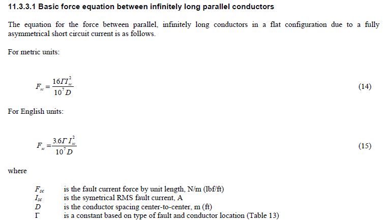
Here is the basic force equation from IEEE 605:
Shor_Circuit_Force_ugip13.jpg


These forces are typically only considered for rigid bus (not for strain bus or flexible jumpers) and the force acts transverse to the length of the bus. Essentially the different phases of the bus are either attracted to each other or repelling each other. Typical values for these loads that I see in design can be anywhere from essentially 0 to 100 lbs/ft of bus or more. If you have a 3 phase bus support only the insulators and top beam will see these loads as they are opposite and cancel each other out (so it's not very impactful on the structure design). However, if you have a single phase bus support, the load will be transferred all the way down through the structure to the foundation.

Here is a video of the force in action, start at 4:03 (or watch the entire video to learn more):
 
phamENG said:
I thought that was typically provided as a reaction from the EE as part of the line and bus design?
My experience is that the structural and EE have to work together on this. The EE is really only concerned with having large enough bus to carry the current safely and efficiently, they aren't necessarily thinking about the structural aspects. I have also never had an EE do the calcs from IEEE 605 for me, they would only ever provide the short circuit design force (and some other parameters referenced in IEEE 605 such as the X/R ration) to use for each particular substation. Often, the bus span is limited by the strength of the insulator. For subs with large fault currents possible I have had to use two (high strength) post insulators at every bus support just to get spans long enough to accommodate the bus layout. I have also had to increase bus size from 4" to 6" for the same reasons.
 
Interesting. Thanks for the info. Not sure how to get there, but I'd love to work in that sector. It would be a nice marriage of my structural work and my electrical work.

In re-reading my initial post, I sort of sounded like an ass. I apologize to the OP and anyone else who thought the same. It was meant as a joke, but reading it a few days later I can see where that tone may not have come through. Short Circuit currents can certainly make things dance around. A comparable example is a distribution breaker being shut out of phase. Had a 4kV breaker try to jump out of its cabinet at me once when the operator paralleled across it a bit too far out of phase. That's essentially an arcing short as the contacts came together.

 
Status
Not open for further replies.

Part and Inventory Search

Sponsor