anedelcu2002
Student
- Apr 24, 2022
- 2
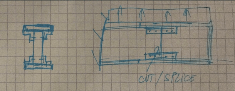
Hello everyone! I have been tasked with designing an I-beam out of a web plate, horizontal flanges and L-shaped corner stiffeners (angles?) as individual parts, with bolted connections being the only ones allowed. The corner stiffeners transmit the loads and hold the web and the flanges together. The objective of the beam design is to resist a nominal bending load (expressed as a distributed force load) while also minimising weight.
While this should be simple in practice by approximating the beam as an integral structure and using bending stress/moment of inertia calculations, the crux of the design problem is that the individual, physical parts I have to use are all approximately two thirds of the expected length of the beam. This means that the web and the flanges will present a splice (or a "cut") at a certain point along the beam - obviously leading to a weakness in the load path transmission. Moreover, the maximum allowable weight constraint leads to an impossibility of placing stiffeners all along the length of the beam in all four corners. As such, a configuration has to be selected so that this fabricated/compound beam can be approximated as an integral I-beam. I have attached two pen sketches of the I-beam cross-section and of the beam loading respectively:
Having played with the idea, I've come up with the following design considerations. Firstly, the cuts in each member will have to be positioned away from each other - if two cuts overlap, a clear weak point occurs with only the stiffener carrying the load across. Secondly, the cuts/splices will have to be placed as far away from the base (clamping) of the beam (where the moment diagram shows the moment is maximum) as possible, so the weak spots are under as little stress as possible. Thirdly, the failure area will generally be the point of a cut, as the weakness resulting from a non-uniform load path will lead to earlier failure than column buckling of the web plate or pure shearing failure of the material. Finally, a stiffener segment will always need to be placed to cover a cut and streamline load transmission.
I have identified two possible failure points: the splice of the lower flange, where the tension from the bending loading could cause the bolts in the stiffener connection to shear off and cause a chain reaction of failure in the cuts; then, the splice in the web plate, where the shear loading could simply displace the web plate segments from one another, leading again to failure. Based on these failure conditions, I have considered two possible configurations: the first one with the web plate cuts at closer to the base of the beam, with the flange cuts further away from the base (lowering the load on the flange splices and thus the vulnerability to the first failure case); the second has the web plate cuts as far away from the base as possible, with the web cuts closer to the base. Both configurations would obviously have stiffeners covering and connecting the cuts and transmitting loads. A possible issue would be the length of the stiffeners, which due to weight constraints can't cover the entirety of the beam and as such might only run from the base to the first cut and then also cover a small segment surrounding the second cut.
This is a fringe design case and I did not find a lot of academic data regarding such constructions. Most of the above comes from intuition, so I would need a sanity check from more experienced engineers. As such, (finally) I have a number of questions:
1. Are my failure predictions for the beam correct? Is there another failure condition I have not considered which is more probable? Moreover, would the solutions I presented be useful in dealing with failure? (obviously, if you can find a better configuration, please say so)
2. Would it be more effective to run the stiffeners from the base to the first cut and then a small segment over the second cut or to cover both cuts with medium-length segments, allowing for some unstiffened web + flange portions (thinking of Saint-Venant's principle for the load distribution here)?
3. How could I estimate a configuration like the two I presented to be an integral beam? I am only a first year aerospace student, and my knowledge of translating such very real problems into theoretical models is very very limited.
If you're still here, thank you so much for reading (and hopefully for answering)!