Continue to Site

Eng-Tips is the largest engineering community on the Internet

Intelligent Work Forums for Engineering Professionals

  • Congratulations SSS148 on being selected by the Eng-Tips community for having the most helpful posts in the forums last week. Way to Go!

Structural Design of Cable and Steel Posts Holding the Cables

Status
Not open for further replies.

M.IDR

Structural
Dec 31, 2020
43
Hello,
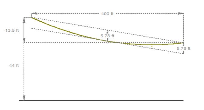
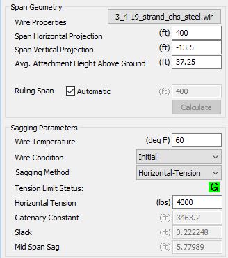
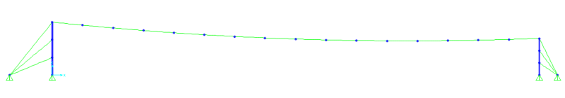
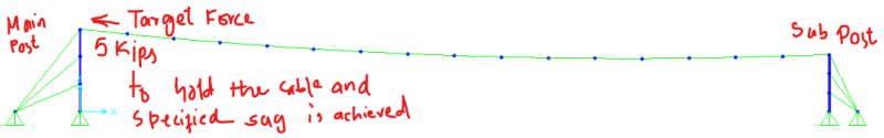
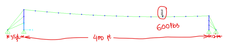
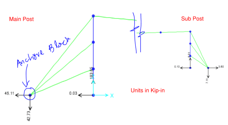
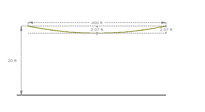
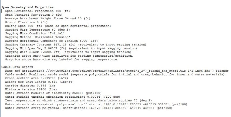
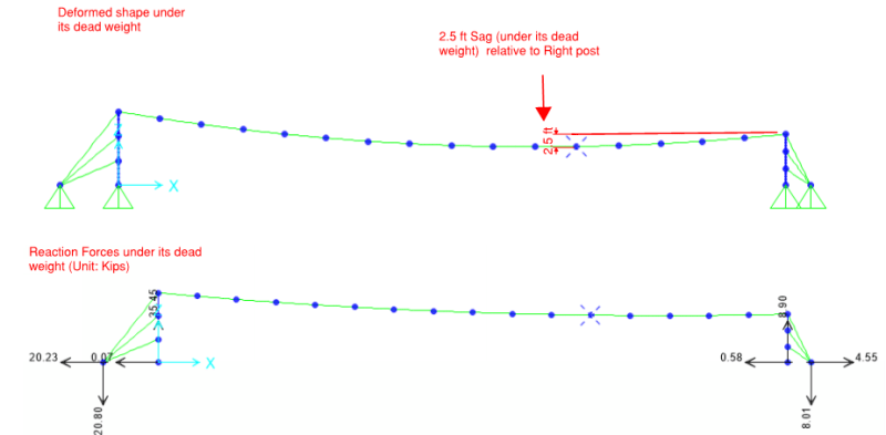
Cables are suspended between two steel posts and anchored as shown in the picture. How these Cable needs to be designed and What are the main components provided in the structural design drawings for construction.
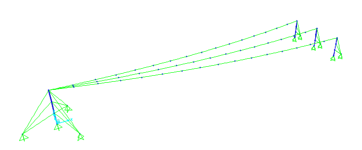
image_jxpc8i.png
3D View.
image_myuz2z.png
Does any one have slightest idea?
 
Replies continue below

Recommended for you

The required tension in the cable(s) needs to be determined so that it performs as expected/wanted. When determining the tension different conditions need to be considered; such as ambient temperature, wind loads, ice loads, etc. all of these things will affect the tension in the cable as well as how much it sags.

Standards/codes used for the design of utility lines might be a good place to start. Check out ASCE MOP 74, Guidelines for Electrical Transmission Line Structural Loading.
 
You should carry out a non-linear analysis of third order in order to correctly simulate the behaviour of the cable structure.
 
If you can get ahold of a copy of AASHTO's sign specification, Appendix A contains an incremental analysis method for span wire structures.

Rod Smith, P.E., The artist formerly known as HotRod10
 
The diagrams you present look as if they could have come from some structural analysis software.[ ] If so, perhaps that software already has some capability for geometric nonlinearity?

If not, my website ( has a spreadsheet that analyses any single cable, with or without a point load somewhere along its length.[ ] However the spreadsheet requires that the cable's end points be rigidly supported, and your diagrams suggest that the end points might have significant elasticity.
 
I have performed Non-linear analysis, to hold down the cable and specified sag is achieved Target force (5 Kips Pull) is applied as shown
image_uwox2i.png

There is a point load also applied during service condition and further sage occurs in the cable.

The Main Post supports Three sub post. Span length of the cable is 400 ft.
image_jjrd3b.png


Now the reaction forces are too high I have to provide anchor block at the Main post for the balancing Cables.
image_lynnai.png


How the structural drawings should be provided to the client for construction? If some one have a sample drawings related to cable structure it would be very much helpful?
 
@Deniel You are right but I am worried that how should the structural drawings should be provided so that the required tension forces are achieved in the cables otherwise there might be consequences.. and the steel post might collapse?
 
5K seems awfully light for something spanning 400'...

Rather than think climate change and the corona virus as science, think of it as the wrath of God. Feel any better?

-Dik
 
Assuming a 3/4" span wire (Single steel wire rope; no other cables), 90mph wind load, 600 lb point load w/ 20 sq. ft. projected area, and stiff (nearly rigid) supports, here are the numbers I get from my analysis spreadsheet:

At 5% sag:
Wire tension - 5.7 kips
Maximum sag - 25'

At 3% sag:
Wire Tension - 9.4 kips
Maximum sag - 17'

At 2% sag:
Wire tension - 14.0 kips
Maximum sag - 13.5'

1/2" span wire (other loading same) at 5% sag:
Wire tension - 5.1 kips


Rod Smith, P.E., The artist formerly known as HotRod10
 
Wazir_Malang said:
I am worried that how should the structural drawings should be provided so that the required tension forces are achieved in the cables otherwise there might be consequences.. and the steel post might collapse?

This is often done with stringing charts. You provide a table that shows how much the cable is sagging (and its tension) based on various conditions (often temperatures). The construction crew would use this chart to identify the condition that matches the "at installation" conditions and install accordingly (either by directly measuring tension or by measuring the sag).
string_chart_1_mq5xlp.jpg

stringing_chart_2_vcup6h.jpg

stringing_chart_f2aovl.jpg
 
@Wazir Malang,

It appears to me that there is something wrong with your statics. The horizontal reaction at the left is 45.11k, while the horizontal reaction at the right is 3.60k, neglecting the minor reactions at the bottom of the two posts.

This cannot be correct since there are no horizontal forces acting on the system. The horizontal reactions at each end must be equal.

Also, the units should be kips, not kip-in.

image_rszkiy.png


EDIT: if 3.60k is the reaction of a single sub post, then the horizontal reaction of three sub posts would be 10.8k, which still does not agree with the left hand horizontal reaction of 45.1k.

BA
 
I have Revised my FEM model, Now the revised results are.
image_xyeqkw.png

image_lbr8wy.png

What you engineers think about it, are the results ok, or should i update my calculations?
 
What is the vertical sag relative to a straight line between the supports? Is the 600 lb load still applied? If the 600lb load is applied, what's the projected area for wind?

Rod Smith, P.E., The artist formerly known as HotRod10
 
Wazir Malang said:
What you engineers think about it, are the results ok, or should i update my calculations?

So you now have 20.23 + 0.07 = 20.3k horizontal reaction at the left end.
And you have 4.55 - 0.58 =3.97k horizontal reaction at the right end. If this is the reaction for one sub post, and you have three sub posts, the horizontal reaction at the right end is actually 3*3.97 = 11.9k. That is a little more than half the left hand horizontal reaction, so your results are not ok.

BA
 
What is the reason for using three ties on each post? Why not just one at the top?

BA
 
Also, is 2.5ft of sag even reasonable over 400 ft at only 4-5 kips of tension. That just doesn't compute for me even from just a self weight analysis. Your pre-load on the cable would need to be significant just to keep the cable sag to that value.
 

It is... it just accellerates to the left...[lol]

Rather than think climate change and the corona virus as science, think of it as the wrath of God. Feel any better?

-Dik
 
Also, is 2.5ft of sag even reasonable over 400 ft at only 4-5 kips of tension.

Unless the left end is much higher than the right end, the tension is very low. By my numbers, with only the load of the wire itself and the wind load on the wire, the tension is 4.3 kips at a 3% sag, equating to 12 feet over the 400 ft span. Less sag, and the tension increases dramatically.

Rod Smith, P.E., The artist formerly known as HotRod10
 
Based on the image posted, the 2.5ft of sag is relative to the horizontal projection of the low post, which is 13.5ft lower than the high post. This sounds reasonable to me (The sag from the straight line between top of posts is 5.78'). I have attached a PLS-CADD/Ultralite report printout(free program from PLS, available here for anyone interested: that looks to be in agreement with what the OP is showing (as well as some screen grabs).
400_ft_span_cable_image_ydzysj.jpg

400_ft_span_cable_image_2_lx7hv6.jpg


Status
Not open for further replies.

Part and Inventory Search

Sponsor